This thread has been locked.

If you have a related question, please click the "Ask a related question" button in the top right corner. The newly created question will be automatically linked to this question.

TPS28225: Switching frequency down to 0Hz / Static condition

Part Number: TPS28225
Other Parts Discussed in Thread: SN6501,

Hello all

I have the following circuit:

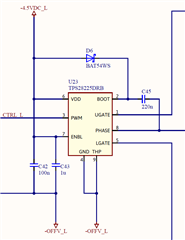
-OFFV_L is -10VDC. The switching voltage is -10VDC/+16.5V

I want to use the circuit with frequencies down to 0Hz so that one MOSFET is continuously turned on. Of courcs this is not possible with the bootstrap circuit.

I thought and tried to suply the BOOT pin with external +22VDC but it did not work (TPS28225DRB gets damaged).

  1. Is it even possible to use the TPS28225DRB in a static condition?
  2. If so, what is the problem with my suggested solution?
  3. How can I change the circuit to achieve the required function?

Thanks for your help.

Best regards

  • Hello Robin,

    You are correct that with the bootstrap high side bias, there will not be the ability to have a continuous on time on the UGATE output.

    The Boot to Phase bias requires a floating high side bias, not referenced to ground, but referenced to the phase node. The SN6501 can be used to generate this high side bias. The bias from Boot to Phase should be at least 4.5V and less than 8V and I recommend it is not less than VDD since there is an internal boot diode.

    If this floating high side bias is provided, the TPS28225 should be able to operate in DC conditions.

    Regards,

  • Hi Richard

    Thank you for your fast and helpful reply. That definitely makes sense with the reference to phase and not to GND. I will have a look at the SN6501. Are there any similar gate driver IC with an included charge pump for continuously switching on the high side FET without  an additional isolated power supply?

    Regards

  • Hello Robin,

    We do not have a driver similar to the TPS28225 with the internal charge pump included, There are some devices such as high side switch and motor drive that have this feature, but they are not a good fit for sync buck applications.

    Regards,

  • Hello Richard

    Ok, last question. To support lower frequencies (> 0Hz) I could increase the bootstrap capacitor. What defines the maximum possible capacity of this?

    Regards

  • Hello Robin,

    Increasing the boot cap is an option but does have tradeoffs, especially if you may operate in high frequency operation and/or narrow pulse widths with  the low side driver. The internal boot diode has a resistance that I expect is 1 to 2 Ohms which will impact how fast the boot capacitor is charged when the LGATE switched the very first cycles.

    I would look at the time constant assuming the boot diode resistance is 1.5 ohms and the target boot capacitor size and see if the UGATE minimum pulse width on the initial starting cycles will allow the boot cap to mostly charge on the initial UGATE cycles. Ideally there would be ~3 time constants to get close to full charge.

    Regards,

  • Thanks a lot for your help!