This thread has been locked.

If you have a related question, please click the "Ask a related question" button in the top right corner. The newly created question will be automatically linked to this question.

BQ79616EVM-021: Waking up BQ79616EVM-021 from Microcontroller. STM32F1xx Series

Part Number: BQ79616EVM-021
Other Parts Discussed in Thread: USB2ANY, BQ79616, BQ79616-Q1

Hi,

Greetings!

I have tested the BQ79616EVM-021 board via USB2ANY and now it works fine. I can see cell voltages in BQAutoEval-1.0.4 GUI. Till now its okay.

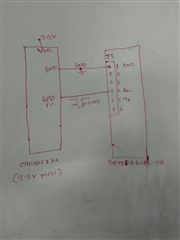
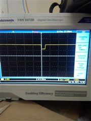
But I want to communicate BQ79616EVM-021 with my Microcontroller. I initiated a WAKE-UP signal of 2.5ms (Active low Signal of 2.5ms) as mentioned in software development guide. But the board was not wake up and LED is not glowing.  I don't know how to wake it up from microcontroller. Please help me in this regard. Please let me know if there are any special voltage requirements to wake it up. or any other command needed. Since it waking up from USB2ANY but not from my microcontroller program.

Thanks!

  • Hi Yogesh,

    Can you share more details about your setup with the microcontroller? The following information would be helpful:

    • What are the connections between your MCU and the EVM?
    • How are you powering the EVM? Could it be current limited?
    • Can you share a scope shot of the WAKE ping?

    Best Regards,

    Kristin Jones

  • Hi,

    1) I have shared the connection diagram here.  Please go through it.

    Simply GND of MCU connected to GND of EVAL board.

    GPIO pin of MCU is connected to Rx Pin of EVAL Board to generate WAKE signal of 2.5 ms.

    I am aware that,

    MCU Tx Should connect to Eval's Rx Pin & 

    MCU Rx Should Connect to Eval's Tx Pin

    But Before that we want to generate WAKE Signal so MCU Tx Pin is configured as GPIO in attached connection diagram and MCU Rx Pin not connected.

    2) I have connected +18V Power between VSTACK & GND Pins & using On board resistor ladder for cell monitoring simulation.

    If Any extra power supply needed then please let me know.

    3) Also I have attached scope screen shot of wake ping signal

    PIc 1


    Above picture shows WAKE ping at MCU pin (This signal is sampled at MCU's GPIO PIn.) here signal switches between 3.3V to 0.2V

    Pic 2

    This signal is sampled at RX test point of EVAL Board. (here signal Switches between 3.3 to 2.2V only.

    Means this signal is not going below 2.2V. 

    Oscilloscope Settings are as bellow

    Amplitude :  2V / units

    Time : 5ms / unit

    Thanks You...

  • Any updates?? We are stuck here. Please let us know how to wake up this board without using USB2ANY.

  • Part Number: BQ79616-Q1

    WE ARE USING

    BQ79616EVM-021 

    FOR BMS DESIGNING

    AND CONNECTED  TX PIN OF STM32 MICROCONTROLLER TO  RX PIN OF EBALUATION BOARD

    AND GENERATING 2.5 MSEC LOW PULSE TO WAKE-UP BOARD

    BUT NOT GETTING RESPNSE 

    PLEASE HELP

  • Hi Yogesh,

    The left side of your scope shots are partially cut off. Can you clarify where the waveform grounds are? I'd like to understand if the second screenshot has a lower peak voltage than 3.3V or if it does not reach 0V when it pulls low. 

    I suspect that this voltage is the issue with your WAKE ping. The UART pins are 5V pins, and the minimum to detect a logic level high is 0.75 x CVDD = ~3.75V. If your maximum voltage is 3.3V from the MCU, then that is not sufficient to wake the device. You'll need to use a level shifter between the BQ79616 and your MCU.

    Best Regards,

    Kristin Jones

  • HI Kristin,

    by level shifting we  have succeeded to wake-up the evaluation board

    but we also are required to remove J18 jumper which connects cvdd to cvdd_co

    is it ok 

  • Hi Yogesh,

    If you are not using the digital isolator on the EVM then there's no issue with removing this jumper. When you remove this jumper you are disconnecting power to one side of the digital isolator. 

    Best Regards,

    Kristin Jones

  • Hi,

    Now I am able to wake up the BQ79616EVM-021 from my MCU.

    Now I set the baud rate 100000 bits/sec.

    and send the Auto Addressing Commands as shown bellow.

    D0 03 4C 00 FC 24
    D0 03 09 01 0F 74
    D0 03 06 00 CB 44
    D0 03 06 01 0A 84
    D0 03 06 02 4A 85
    D0 03 08 02 4E E5
    90 00 03 08 00 13 DD
    90 02 03 08 03 52 64
    C0 03 4C 00 F8 E4

    then Send Read Cell voltage commands  as shown bellow.

    D0 00 03 0A B8 13
    D0 03 0D 06 4C 76

    Delay_1mS();


    C0 05 68 1F 42 2D

    but no response received from BQ79616EVM-021. 

    Also Baud Rate for UART Communication is not mentioned anywhere not a single time. 

    So please guide me what is standard baud rate and why not respomnce getting from BQ79616EVM-021. 

  • Hi Yogesh,

    The baud rate is listed in the datasheet, as is the auto-addressing procedure. The datasheet is necessary if you're writing custom software for the device on a different MCU than the Hercules Launchpad. 

    There are a couple of issues with your auto-addressing procedure. First, you are only sending a single command for the dummy read/writes. These should be 8 separate read/write commands. The bigger issue is the two single device write commands. You need to set all of the devices as stack devices except for the base device, and then set one device as the top of stack. If you have 3 devices in your stack, your commands are leaving device 0x01 as a base device. This will cause issues with the communication. The easiest way to fix this is to add a broadcast write to address 0x0308 setting all devices at a stack device and not top-of-stack before your single device write commands.

    Best Regards,

  • Part Number: BQ79616EVM-021

    we are sending following command sequence to bq79616-021 evaluation board

    at 100000 baud rate with 8 data bits parity none and one stop bit

    BMS Auto Addressing Command Sequence 
    {D0}{03}{4C}{00}{FC}{24}
    {D0}{03}{09}{01}{0F}{74}
    {D0}{03}{06}{00}{CB}{44}
    {D0}{03}{06}{01}{0A}{84}
    {D0}{03}{06}{02}{4A}{85}
    {D0}{03}{08}{02}{4E}{E5}
    {90}{00}{03}{08}{00}{13}{DD}
    {90}{02}{03}{08}{03}{52}{64}
    {C0}{03}{4C}{00}{F8}{E4}

    //*******************************************************
    //*******************************************************

    BMS Read Cell Voltages Command Sequence 
    {D0}{00}{03}{0A}{B8}{13}
    {D0}{03}{0D}{06}{4C}{76} Delay_1mS();
    {C0}{05}{68}{1F}{42}{2D}
    but not getting any response from bq79616-q1
  • Hi Yogesh,

    This question was posted as a new thread but is identical to your question above. Please see my response above.

    Best Regards,

    Kristin Jones

  • Dear Kristin,

    Thanks for the showing the auto addressing issues in my procedure I will get back to you soon.

    And I already mentioned that I am using STM32F1xx Series MCU (NOT USING Hercules Launchpad)

    Also we are writing custom software for the device.

    Also please share the link of datasheet you mentioned in your reply. So that I will be in sync with you. As I did not found Baud rate.

    Is it okay to send data with baud rate of 115200 bits/sec ??


  • Hi Yogesh,

    The expected baud rate is 1Mbaud. This is the link to request the datasheet: https://www.ti.com/licreg/docs/swlicexportcontrol.tsp?form_id=305269&prod_no=BQ79616-Q1-Design-Documents&ref_url=app_bms_bms-bap

    Best Regards,

    Kristin Jones