This thread has been locked.

If you have a related question, please click the "Ask a related question" button in the top right corner. The newly created question will be automatically linked to this question.

BQ25887: Leakage current of IC when not powered

Part Number: BQ25887

We are using the BQ25887 to charge an off-board device.  One issue we are observing is that when the "charger system" (which includes the BQ25887) is unpowered and the device to be charged is still attached to the charger, the device to be charged has a ~800uA current draw on the "BAT" line. 

To troubleshoot, we have removed TVS21 and C53 and the current draw remains, so the current draw is from the BQ25887.  

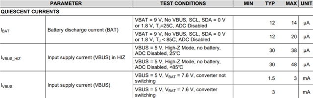
I could not find any "unpowered" behavior documented in the datasheet.  Do you have any further information on why this could be happening AND do you have any suggestion as to how we could remove this issue?

Thanks!

  • More information -

    If the Device to be Charged is plugged into a powered down Charger, then there is no leakage current out of the device.

    However, if the Device to be Charged is charging/sitting on a powered BQ25887 and then power is removed, then the leakage happens.  

    So it seems as if there is a meta-state or power-down issue that we are inducing into the BQ25887 that is causing it to not power down into the Hi-Z state.  Does that make sense?

    If so, do you know of a workaround for this?

  • Hi David,


    The typical battery quiescent current and input quiescent current for various cases are shown in the EC table:


    Just to make sure I understand correctly, it sounds like you are describing 2 cases:

    1. Initially, the 5V input at the VBUS pin and the device to be charged are both disconnected. Then, the device to be charged is plugged in and connects to the BAT pin. In this state, the quiescent current is very low.
    2. Initially, the 5V input at the VBUS pin and the device to be charged are both connected. Then, the 5V input is removed. In this state, the quiescent current is ~800 uA.

    Is this correct? When you say the BQ25887 is unpowered, do you mean that the 5V input is physically disconnected/removed, or is the 5V input just turned off somehow? By the way, what is the "device to be charged"?


    In the ~800 uA case, please measure the VBUS and VBAT voltages, as seen by the BQ25887. Also, did you change any of the register settings, or are they still at the default settings after a POR?


    Best regards,

    Angelo

  • Angelo -

    Thanks for the response.

    Your restating of the two cases is mostly-correct.  I am not concerned about the quiescent current.  The value I am trying to minimize is "IBAT"  We meet the IBAT figure in case 1.  In case 2 IBAT is approximately 850uA.

    When you say the BQ25887 is unpowered, do you mean that the 5V input is physically disconnected/removed, or is the 5V input just turned off somehow?
    Disconnected/Removed

    By the way, what is the "device to be charged"
    2 LiPo batteries in series.

    please measure the VBUS and VBAT voltages, as seen by the BQ25887
    VBUS (measured at C61): 0V - as expected, 5V has been removed.
    VBAT:  (measured at TP136):  8.25V - as expected, this is the series voltage of the batteries on the Device to Be Charged


    Also, did you change any of the register settings, or are they still at the default settings after a POR?
    Changed settings:
    /Default Values
    #define DEFAULT_CELL_VOLTAGE_LIMIT 0xA0 //4.20V
    #define DEFAULT_CHARGE_CURRENT_LIMIT 0x04 //Disable HiZ, Disable ILIM Pin, 200mA charge current
    #define DEFAULT_INPUT_VOLTAGE_LIMIT 0x84 //0b10000100 - VINDPM enabled, disable load, out of audio enabled, 4.3V
    #define DEFAULT_INPUT_CURRENT_LIMIT 0x12 //0b00010010 - Force ICO, do not force PSEN, disable ICO, 700mA
    #define DEFAULT_PRECHARGE_AND_TERMINATION_CONTROL 0x00 //Precharge - current limit, 50mA, CV termination current 50mA
    #define DEFAULT_CHARGER_CONTROL_1 0x88 //0b10001000 - Enable termination, STAT function, WDT disabled, safety timer on, charge timer 5 hours, safety timer alwayw on
    #define DEFAULT_CHARGER_CONTROL_2 0x37 //0b00110111 - Disable PSELL on plug in, thermal 120C, charge disable, precharge 3V, cell recharge 200mV
    #define DEFAULT_CHARGER_CONTROL_3 0xC2 //0b11000010 - Enable PFM, Reset WDT, Top of timer disabled
    #define DEFAULT_CHARGER_CONTROL_4 0x15 //0b00010101 - JEITA high 8.3V, JEITA high 100%, JEITA Low 20%
    #define DEFAULT_CHARGER_MASK_1 0xF8 //0b11111000 - No INT other than CHRG_STAT
    #define DEFAULT_CHARGER_MASK_2 0x96 //0b10010110 - No INT pulses
    #define DEFAULT_FAULT_MASK 0xD8 //0b11011000 - No INT pulses
    #define DEFAULT_ADC_CONTROL 0xB0 //0b10110000 - ADC on, continuous, 12bit resolution
    #define DEFAULT_ADC_FUNCTION_DISABLE 0x00 //0b00000000 - All conversions on
    #define DEFAULT_CELL_BALANCING_CONTROL_1 0x2A //0x00101010 - 40mV exit, 2min interval for entry, 2min interval for measure, 1s measure delay
    #define DEFAULT_CELL_BALANCING_CONTROL_2 0xF2 //0x11110010 - No prequalification, 60mV difference to start balancing
    #define DEFAULT_CELL_BALANCING_STATUS_AND_CONTROL 0xC0 //0x11000000 - charge disabled during balance voltage measurement, enable auto balancing,
    #define DEFAULT_CELL_BALANCING_MASK 0x3F //0x00111111 - No INT on balancing

  • Angelo -

    Here is some more information.  I thought there might be some weird fall time issues on the input voltage of the BQ25887.  Below are the experiments showing the results.  So there was a weird issue as the bus was back-fed by the Device To Be Charged.  However, I was able to remove the slow fall time issue and the spurious load on VBAT still remained.   Not sure if that helps, but it is more information for you.

    • Check fall times of 5V and 3.3V when power is removed. 

    5V Bus (A1) and 3.3V Bus (A2) - Normal circuit configuration.  Voltages held at ~1V for both for about 2 minutes after power removed as back fed from battery on tag


    5V Bus (A1) and 3.3V Bus (A2) - 100 ohm load on 3.3V and 50 ohm on 5V bus.  3.3V bus goes to 0V within 5ms.  5V bus goes to 0V in 25ms.  Still have ~860uA load on Vbat.

    • So with experiments above, the fall time was weird.  However, cleaning it up does not remove the problem.
  • Hi David,


    Thanks for the information. I don't see C61 and TP136 in the schematic in your original post, but your VBUS and VBAT voltage measurements make sense.


    I will try to duplicate your results on an EVM using your register settings. Can you confirm that there is nothing else connected to the VBAT_0 net in your schematic, which may not be visible in the screenshot in your original post? I would like to isolate the BQ25887 so we can be sure that the ~850 uA IBAT quiescent current is through the BQ25887.


    Also, is there any change in the IBAT quiescent current (~850 uA) if you disable the ADC or enable HIZ mode before unplugging the 5V input at the VBUS pin?


    Best regards,

    Angelo

  • I don't see C61 and TP136 in the schematic in your original post, but your VBUS and VBAT voltage measurements make sense.

    Sorry - we have a multi-channel device and I measured on Channel 1; while the schematic I provided is Channel 0.  C61 is equivalent to C43 and TP136 is equivalent to TP97.

    Can you confirm that there is nothing else connected to the VBAT_0 net in your schematic, which may not be visible in the screenshot in your original post?
    Nothing else is connected.  The screenshot shows the only things connected.  In addition we have tested with the TVS loaded and not loaded with no change in behavior (the TVS has a datasheet leakage of 10s of nA as well, so should not be a problem).

    Also, is there any change in the IBAT quiescent current (~850 uA) if you disable the ADC or enable HIZ mode before unplugging the 5V input at the VBUS pin?
    Standard SOP for our FW is to enable HiZ at end of charge (setting the CD pin high in addition CHARGER_CONTROL.EN_CHG is set to '0').  The ADC is still enabled.  In this case, the 860uA is there.

    As a test I tried HiZ enabled and ADC disabled.  Results: current is ~20uA.  So it appears that the issue is related to the A/D being enabled.

    This points to some sort of workaround.  However, for our particular application, this is a no go:
    1 - Power can be removed at any time, not just at the end of a charge cycle.  So we would be leaving an entire use case susceptible to this problem.
    2 - We use the A/D readings to determine if a device has been plugged in and needs to be charged.  As such we need to have the A/D continuously running.

    Hopefully with this information we can figure out what is going on now.

    Thanks!

  • Further information - I switched the AD mode from "Continuous" to "One Shot".  I made no other FW changes or HW changes.  The problem appears to be gone.  I can pull power at any time in the charge cycle and the current goes to ~20uA when the power is removed. 

    So it appears there is a FW workaround.  

    Before moving forward, I would like know why the problem (if it is one) is actually happening.

    Thanks!

  • Angelo -

    Were you able to hunt down any information on this?

  • Hi David,


    Thanks for sharing your findings. This behavior makes sense because the ADC circuitry is still active and drawing some current from the battery after the 5V input is removed.


    I tested a BQ25887 EVM and see similar results when the ADC is enabled in continuous mode. If the ADC is disabled or changed to one-shot mode, then the IBAT quiescent current falls to ~20 uA, which is consistent with your observations.


    Best regards,

    Angelo

  • Angelo -

    That's good you can recreate it on your end.  If you think the behavior makes sense, I suppose that answers all of my questions.  Thanks.