


Hi,
I want to use TL5002 IC to control Input voltage of a Buck converter. Let me explain my where I am using this buck converter,
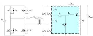
I have a Phase shifted full bridge (PSFB) converter converter (6 KW)working with Input to the PSFB being Solar PV Panel whose Voc is 800V and I have a transformer ratio of 1:1.43 and at the output of a transformer being the full bridge rectifier. So with some simulations I found out that the voltage across the diodes is going around 2300V (i.e 2*1.43*800) when the input is 800V. But the SIC DIODES which we have chosen are only 1700V. So we thought of using a active snubber. Hence we have a diode Ds1 and Cs for clamping the voltage to 1300V (when the input is 800V). Now this energy stored in capacitor Cs will be sent to DC Bus of Cf as shown in below diagram.
So now I want to control the switch of buck converter as below (shown in figure),
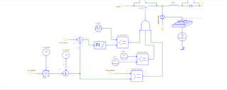
snub_sense is the voltage across Cs (clamping capacitor) and V_in_sense is the PV Voltage sensed. So essentially I want to use a Controller to control the input voltage of buck converter to a specified value, for examples if the input PV voltage is 800V then without snubber the voltage across the each rectifier diodes will go to 2*1.43*800 = around 2300V, so I want to regulate the voltage across Cs (clamping capacitor) such that the voltage of 1300V is maintained across that capacitor and hence the voltage across any of the diodes will be clamped to 1300V and now if the voltage across Cs goes below 1300V then I want to switch off the pulses to the buck converter switch. So the above explanation is my application and hence I want to use TL5002 for the input voltage control of buck converter. Where to the INV PIN of TL5002 the sensed the voltage across Cs (clamping capacitor) (using differential amplifier of 1/100 gain) is given, and the voltage across PV is sensed using differential amplifier (with gain 1/100) and then multiplied by 1.43 and then using a reference generator IC a 1V is added (so that when 800V is the input, ((800*1.43)+100) = 1244 V is the voltage across Cs)which is then given to NI pin of TL5002. and to the compensation PIN I am planning to use the compensation (PI) that I have used in the simulation (of same value). And then output of TL5002 will be anded to the comparator again as shown in second figure and given to a gate driver. So I want to understand from you that whether this approach to control a input voltage of buck converter will work?
or Is there any other IC which we can use to control the input voltage of Buck Converter?
Thank you
Vijaymahantesh V Surkod
