This thread has been locked.

If you have a related question, please click the "Ask a related question" button in the top right corner. The newly created question will be automatically linked to this question.

TPS548B22: TPS548B22 has output only 0.43V

Part Number: TPS548B22

Hello Admin,

I have a question about using TPS548B22 for Xilinx FPGA.

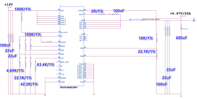
0. Web bench setting is like the below.

- Input: 12-14V

- Output: 0.87V

- Output current: 25A


1. Out circuit diagram is different from Web bench output and it always outputs 0.43V.
what's wrong with our circuit?
All things must same with Web bench, Such as input and output capacitor and any resistors?

2. How can I change my schematic for better performance and stable output for 0.87V?

Wait for your kindly reply

Thanks.

  • I try to change RSP, RSN resistors, and FSEL resistor but the output was not changed from 0.43V

    EN_UVLO's maximum input voltage is defined as 5.5V on the datasheet. so 51K pull-down resistor add to EN_UVLO

  • Hello,

    To answer your questions: 

    1.The circuit does not need to match the Webbench output provided you have sufficient input/output capacitance and follow the guidelines detailed in the datasheet.  As far as your output voltage goes, 0.43V is less than the minimum reference voltage of the device, which should not be occurring. Your reference voltage is set to 0.5995V and the resistor divider from Vout to RSP/RSN appears to be the correct ratio to achieve 0.87V of output voltage. Looking at the switching frequency selection, you appear to have enough margin to avoid the minimum on-time controller limit as well. Do you have any data such as SW node waveforms that may provide better insight as to why the regulation is not being achieved? As you mentioned in the comment, the EN pin does need a divider as 12-14V does violate the maximum pin voltage rating of EN/UVLO.

    2. As far as performance goes, the schematic appears to be good for 0.87V. Are there any parameters such as transient response or ripple for which you must optimize the design?

    Alec Biesterfeld

    BSR-MV-Applications

  • I added the bypass capacitor on BP(PIN31).
    As far, It seems to be working well.

    In my opinion, the missing Bp Pin's bypass capacitor was the problem.

    I will do more tests and reply to you.

    Thanks for your help.

  • Great to hear! That is interesting behavior, but bypassing BP is necessary. I will note that. Please reach out with any additional questions!