A related question is a question created from another question. When the related question is created, it will be automatically linked to the original question.
If you have a related question, please click the "Ask a related question" button in the top right corner. The newly created question will be automatically linked to this question.
Thanks for your reply. For our application, TPS73801-SEPs are used for the conditions below. Maybe you can help to choose some representative conditions to show PSRR plot. If you have any suggestion about Cout to get better performance of TPS73801-SEP, please also advice. Thanks a lot!!
Typically lower Vout will have better PSRR performance.
Lower load will have better PSRR performance.
Higher Vout capacitance will have better PSRR performance
Will need minimum headroom to insure Vin ripple doesn't get within dropout region.
I will not be able to test all of the above conditions in the near term as it is fairly time consuming changing board configuration. Will also be subject to availability of appropriate components.
BTW, the minimum Cout recommended is 10uF. Your case 3 only has 1uF, but may be okay with such a light load.
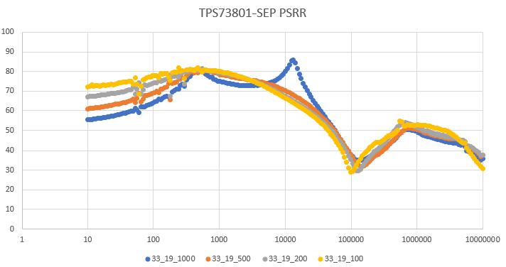
I have lab time tomorrow, and will target the last case of 3.3 vin, 1.9Vou, 10uF and 500mA.