This thread has been locked.

If you have a related question, please click the "Ask a related question" button in the top right corner. The newly created question will be automatically linked to this question.

BQ24079T: EVM test charge function

Part Number: BQ24079T

Hi Sir,

My customer is using BQ24079T EVM to test charge/no charge function. We found charge current status unstable when TS voltage at 1.36V. As I know the system shouldn't charge at TS 1.36V, could you help to check?

There is a video for you reference.

https://tidrive.ext.ti.com/u/_297bI1veyjtb3tu/2b993653-576c-4804-a3b2-18d08f3b0270?l

Test condition:

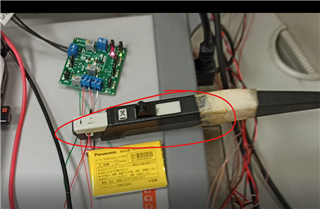
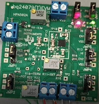
  1. Power supply to supply 5V for TI BQ24079TEVM
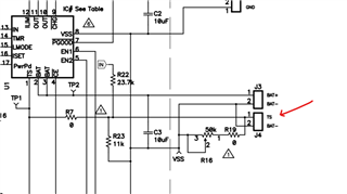
  2. Adjust TI BQ24079TEVM R16 to let TS voltage at 1.36V
  3. Test MODE(ILIM), EN2(1) and EN1(0)


Thank you.

  • Hi.

    I see you have a current probe, can you provide current waveforms for the IN, OUT, and BAT pins connections? If possible, can you connect a power supply to the TS pin and drive this with 1.36 V with a low current limit (20mA should be sufficient for a max). 

    What battery voltage does this occur at?

    Best Regards,

    Anthony Pham

  • Hi Anthony,

       Thanks for your feedback.


    I see you have a current probe, can you provide current waveforms for the IN, OUT, and BAT pins connections?

    • What’s current waveforms? How to measure it? Could you explain more detail to me?


    connect a power supply to the TS pin and drive this with 1.36 V with a low current limit (20mA should be sufficient for a max)

    • The EVB will be power ON when power supply offer 5V to “J1”. At the meantime, TS has voltage and we can adjust R16 to decide TS voltage.

    I don’t know why TS need to connect a 1.36 V? If you still suggest to do it. Could you advise more detail about how to do it? Thanks.


    Best Regards,
    Johnny Kao

  • Hi Johnny,

    From the video I saw the current probe circled in red. Is this attached to an oscilloscope? If you're able to connect this to an oscilloscope, it may tell of the current going into the battery. 

    I don’t know why TS need to connect a 1.36 V? If you still suggest to do it. Could you advise more detail about how to do it? Thanks.

    With this, we can ensure that the TS pin on the device sees a stable voltage that is not dependent on the board components. It's also easier to sweep across voltage to verify the thresholds of the device.

    There should be a pin you can apply a voltage to on the EVM. as shown in the schematic snippet. You can apply a voltage here that the TS will see. 

    What is the voltage seen on the battery?

    Best Regards,

    Anthony Pham