This thread has been locked.

If you have a related question, please click the "Ask a related question" button in the top right corner. The newly created question will be automatically linked to this question.

TPS546D24A: 4-Phase Slave Address not responding

Part Number: TPS546D24A
Other Parts Discussed in Thread: PMP21814, , TPS546D24

Hi Support Team, 

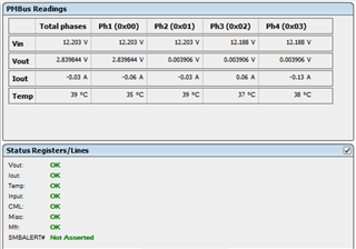
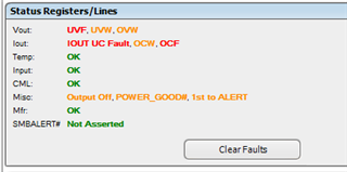
I follow the PMP21814 to implement the 4-phase circuit.  However, I am unable to read any slave device via Fusion GUI. 

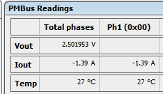
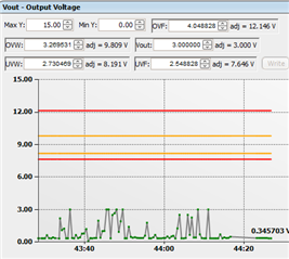
My board can operate well in a standalone mode; e.g. VOUT can bel changed via PMBUS. 

Please advise what is the critical signals for the slave devices to work.  I did check the following signals which look good: 

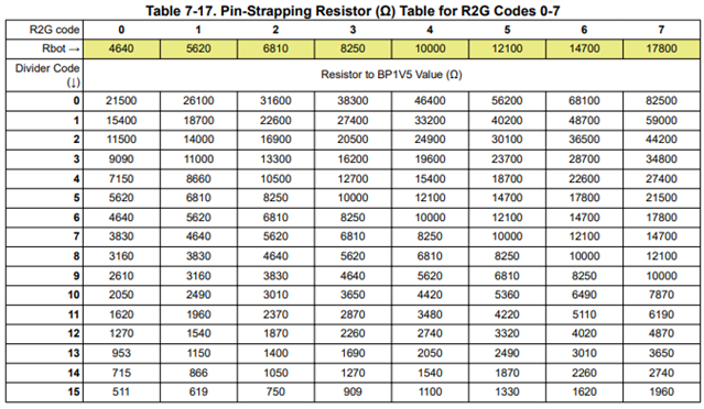
1. MSEL2 (RBOT) of Master is set to 8.25K  

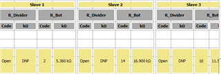
2. MSEL2 (RBOT) of Slaves are set at  5.36k,11.5k, 16.9k according to GUI and reference design

3. GOSNS of Master is tied to ground 

4. GOSNS of Slaves ae tied to BP1V5 

5. VSHARE are connected to all devices 

Am I missing any set-up which stops the Master Device to get data from Slaves? 

The current WEBBENCH support 2-phase only.  Is it possible to configure WEBBENCH to 4-phase mode?

Thanks,

Albert 

  •  

    It looks like you have the incorrect MSEL2 resistors.  With an overcurrent limit of 40A/52A, the resistor values should be

    6.81k (Device 1) 68.1k (Device 2) and 31.6k (Device 3) 

    In fact, the values you listed are not on the resistor selection criteria for the TPS546D24A at all, so I am not sure where they came from.

    Also, make sure the BCX_CLK and BCX_DAT pins of all of the devices are connected together, this is how the devices of a stack communicate and they will not start-up if the BCX is not connected.

    Also, make sure their SYNC pins are connected together.  The follower devices will not generate an internal clock and will require an external SYNC to start-up.

  • Interesting.  The MSEL2 values came from the TI 4-phase reference schematic.  I also confirm these values with Fusion GUI. 

    Will try out your suggestion.  Thanks.  

    One more question, when I operate it in Standalone mode, the output current is negative number. 

  •  

    In the FUSION GUI,

    1) Are you using the latest version of the FUSION GUI?

    2) Are you using the TPS546D24 or TPS546D24A?  They use different resistors.

    Regarding the current:

    The current sense element in the TPS546D24A is 0.5mOhms and it is able to measure both positive and negative currents.  Offset errors due to differences in the current flow through the IC in production testing and an application board are common.  The negative current reporting is a result of that residual offset.

  • For 4-phase circuit, I am using TPS546D24 due to IC shortage.  What is the proper resistor values?

    Should I change it to TPS546D24A?  What is the major difference?  

  • The TPS546D24 uses a completely different set of programming resistors for pin-strap selection.  The MSEL2 selection you have for Device 0 (Rbot = 8.25k) is not selecting a 4-phase stack with the TPS546D24.

    In addition to using different programming resistors, the TPS546D24A's pin-strap programming is not rated for use through the product life or the full temperature range.  Pin Strap values must be stored to NVM and Pin Strap disabled by setting PIN_DETECT_OVERRIDE = 00h as part of the production flow.

    The TPS546D24A also includes a number of robustness improvements for non-standard events like improper PMBus transaction traffic, accidental shorting of BCX pins, brown-out conditions that result in follower devices on a stack falling below ULVO without triggering the UVLO of Device 0, and the like.

    I would strongly recommend using the TPS546D24A.

  • I finally changed to TPS546D24A.  The 4-phase is working now!  I used 6.81k (Device 1) 68.1k (installed 66.5K instead for Device 2) and 31.6k (Device 3).  I don't have 68.1K resistor in my lab and will re-install 68.1K later. 

    I still cannot get Vout to my expected output ( e.g. 1.8V to 2.6V) due to a sync error.   The Vout stays around 0.4V no matter what I changed in configuration setting.   Is it caused by wrong value of MSEL2 as I described above?  Thank you.  

  •  

    Are all of your SYNC lines connected to each other?

    If the issue was the MSEL2 resistor, it would be reported as a POR (Power On Reset) fault not a SYNC fault.  A Sync Fault occurs when one or more of the devices in the stack are not receiving a SYNC signal for their CLK.  Device 0 should be outputting a SYNC for the remaining devices to receive, unless Device 0 is programmed to SYNC_IN via the resistor divider on ADRSEL, in which case, they would need an external CLOCK to synchronize to.

  • The SYNC are tied together. 

    I did get everything working at cold boot once or twice (as shown below). The output is then disabled (e.g. SYNC Fault) after 1~2 min.


       The SYNC is set at auto-detect.  So, I believe the circuit is working but some setting/resistor are wrong. 

  •  

    Click on the Status button on the lower left side of the page to bring up the status.  It will provide the detailed status from each phase so we can see which device or devices in the stack are reporting a SYNC fault.

    That will bring up the status page, which includes a detailed list of the status of each phase in the stack, so we can see where the SYNC fault is coming from.

  • I did check status tab and it said 4 devices failing SYNC. I don't understand on Mfr Fault. 

  •   

    Let's try something.

    First, check the SYNC signal to make sure Device 0 is generating a SYNC for the other 3 devices.

    Second, check the enable timing between the 4 devices.

    Is a single enable being used for all of the devices?

    Does each device have it's own enable / UVLO or are they connected together?

    As an experiment, you can force Device 0 into SYNC_OUT, which will generate a SYNC as soon as the converter powers up and not wait for the Enable of the output.

    1) In the Configuration tab, go to PIN_DETECT_OVERRIDE and change SYNC_CONFIG from Pin Detection to NVM

    2) Also in the Configuration tab, go to SYNC_CONFIG and change SYNC from Auto-detect to SYNC_OUT

    3) Write to Hardware, store to NVM, and then power cycle the converters.

  • I still have problem with CML after I tried SYNC and tied-EN/UVLO.  The UVLO is measured around 3.4V. 

    I set OVERRIDE to NVM for all settings.  I still get CML and Processor fault. 

    We cannot get TPS546D24A from TI store. 

    Can we use TPS546D24 in 4-phase mode?  What is the resistor value? 

    It is not documented in TPS546D24 user manual.  

  •  

    If you are seeing a PROC Fault, I suggest you check the voltages on the BCX_CLK and BCX_DAT pins.  The TPS546D24 can experience a PROC logic fault of the BCX pins are held low due to a short.  This can also trigger a CML communications fault.

    For the TPS546D24 using 4-phase the MSEL 2 resistors would be:

    Device 0 - 5.36k to GND, 4.87k to BP1V5

    In the TPS546D24, the MSEL2 resistor to ground sets current limit and soft-start time while the divider selects the number of devices in the stack.  This was changed in the TPS546D24A to allow more applications to not require an MSEL2 divider.

    Device 1 (90 degrees delayed from Device 0) MSEL2 to GND = 4.87k

    Device 2 (180 degrees delayed from Device 0) MSEL2 to GND = 8.66k

    Device 3 (270 degrees delayed from Device 0) MSEL2 to GND = 7.15k

  • The Vout is ON/OFF intermittently.  The turn off is due to UVW and other voltage fault; no more CML fault. 

    Do I have to tie Master EN/UVLO to all slave?

    I tied the Master EN ( at 3.54V ) to slave 1, the voltage drops to 1.05V.  

    Currently all 4 devices tie to its own voltage divider ( e.g. 3.54V). 

  •  

    While is it preferred that all devices in a stack share a common EN line, it is not required, and I don't think that is your issue here.  The list of warnings and faults - Under Voltage, Over Voltage, Under Current and Over Current suggests that the control loop is likely unstable.

    Have you tried the compensation design tool linked in the TPS546D24A datasheet to select a compensation option?

    If so, what switching frequency and compensation code are you using?  If not, I would suggest trying to use it to select a compensation option that can provide a stable output voltage.

    Are you using the MSEL1 resistor table from the TPS546D24A to select the compensation resistors for the TPS546D24?

    As with MSEL2, MSEL1 resistor programming is different between the TPS546D24 and TPS546D24A, so similar resistors will be selecting very different compensation options.

  •   

    I see this issue is still open.  Were we able to resolve the issue you are seeing?

  • We still have SYNC issue with 4-phase configuration.  We can change Vout to what we want but the SYNC fault occurs periodically.   We don't have similar problem with our 2-phase board.   Can we debug issue via email instead?  Thank.  

  • Hi Earl,

    Please wait for Peter's reply on Monday US time.

    Thanks,

    Lishuang

  •  

    If you can send me a message here with your e-mail address, I can see if I can assist you.

    Have you tried setting the stack controller (Device 0) as SYNC_OUT using either PMBus or the ADRSEL resistor divider?

  • Thank you.  My email is albert_man@yahoo.ca.  

  • Hi Earl Mai,

    I believe Peter had contacted you or will contact you soon.

    Let's close this thread.

    Thanks,

    Lishuang