This thread has been locked.

If you have a related question, please click the "Ask a related question" button in the top right corner. The newly created question will be automatically linked to this question.

LMQ61460: Drop Vout when Vin is above 21V

Part Number: LMQ61460

Hi TI team,

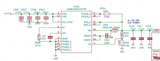
I'm testing my first circuit with LMQ61460 and I observe that everythings works fine if Vin is under 21V. My configuration i 5A@5V. I've succesfully tested loads up to 5A at 20V input but when I rise input voltage above 22V IC drops output to 0V. I have no idea what's going on. Please point me what to check. Below is my circuit. Thanks in advance.

  • Hi Michal,

    I would increase the input capacitance to the minimum 10uF of ceramic following the datasheet recommendations. At higher input voltages the MLCC will derate significantly so having larger input caps will help manage the ripple per Section 10.2.2.5

    What is your ambient operating temperature? As for the basic operation of 24Vin|5Vout|5A|400kHz, if your circuit follows similar PCB and thermal layout considerations like the EVM, you should be able to push 5A even at elevated temperature of 110degC (Figure 10-2). 

    I would start out at 24Vin|5Vout and no load. Then start slowly ramping up the load current to see when the output voltage drops. Right now the schematic looks okay and there isn't any clear signs of why you wouldn't be able to regulate at higher input voltage.

    Regards.

    Jimmy

  • Hi Jimmy, thanks for quick reply!

    Now input caps are 10uF + 2,2uF

    Ambient temperature is 20°C, I've measured IC temperature at 4A load: 55°C. f=400kHz

    I'm not able to set 24V and no load because on that conditions output is 0V :-(

    I took some measurements - look at photos.app.goo.gl/bFjxUJBUysnVQVPd7

    Photo001 and 002: Under 21V even load is 4A output voltage still remains 5V (almost independent from load current). Ripple voltage is within 50mV. It seems that turning off output voltage only depends from input voltage, not load current.

    Photo003 and 004: When I turn ON input voltage (24V) at no load(!) then output voltage first go to 5V and next slow rises to zero (-1V/s), when load is 100mA output voltage goes very fast to zero. Looks like output cap discharging at OFF state of IC power stage.

    Photo 004: See what is happen when I slowly rise input voltage and then fall it

    Photo 005: Same as 004 but at 4A load and detailed. There are oscillations between 21,2V and 22,8V. Under 22,8V oscillations disappear and output voltage is 0V.

    See also my layout - I have got a lot of space on board so power planes are big enough to carry high currents.

    I wonder if reason may be overheating chip during manual soldering (with hot air set to 240°C). Maybe I should replace the chip

    On the same board and power supply are present two TPS5430DDAR, both works fine.

  • Hi Michal,

    Thanks for the detailed scope images and yes I can see that the at input voltages above 21V there seems to be issues with regulation for whatever reason.

    1. Can you provide me the datasheet of the external power inductor that you used? 
    2. Can you try to reflow and replace the chip with a new device and retest functionality? It is possible that overheating the part may cause internal damage that could impact functional operation.
    3. The device should be able to regulate 24Vin|5Vout|400kHz for the full operating current as shown in Figure 10-18 load regulation. It sounds like it's only an input voltage issue and not a load current issue. What input supply are you using and is it stable? 

    Regards,

    Jimmy 

  • Jimmy, after replacing the chip everything works fine. Looks like it was overheating effect - good experience for me. New IC was successful loaded 4 amps for 10 minutes at 24V.

    BIG thanks to you for your commitment to solve the problem. Generally it is very nice chip, small and powerful. This was a test before using it in future projects