Other Parts Discussed in Thread: UC1901, UC1843,
Hello,
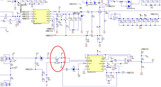
I have a question regarding the turn ratio of the impulse transformer used in the following ref design :
I'm actually worried about the turn ratio of the transformer used with the UC1901.
Here is the impulse transfo I’m worry about:

The transformer turn ratio is 1:1, as shown below
![]()
But from the UC1843’s datasheet we can see that the error amplifier track 2.5V :
![]()
And from UC1901’s datasheet we can see that the output swing of the AM signal, representating the error signal to be feeded in the UC1843, can goes as low as +-1V6 (don’t know under which conditions) :
The output is imply redressed by a diode and a capa at the output of the impulse transfo (AM demodulator)

I'm not 100% sure how to interpret this. of courser, with a ouput swing of the AM modulator at 1.6V , then we will never reach the 2.5V of the error amplifier of the UC1843. Even with the typical value of 2.8V, with the voltage drop of a schotty diode, we are close to the 2.5V of the error amplifier of the UC1843.
So my question, this design is it well done? Shouldn’t we have a turn ratio of 2 in the impulse transfo to get a amplification by 2, so that we are 100% sure to reach the 2.5V after the diode D9 above?
Hope the question is clear,
Thanks!
JF.

