This thread has been locked.

If you have a related question, please click the "Ask a related question" button in the top right corner. The newly created question will be automatically linked to this question.

TPS549D22: Output voltage ripple has a subharmonic oscillation

Part Number: TPS549D22

Dear team

Customer found out that the output voltage ripple has a subharmonic oscillation on the TPS549D22RVFR.Is it normal? Are there any no stability issues?

As below is detail information :
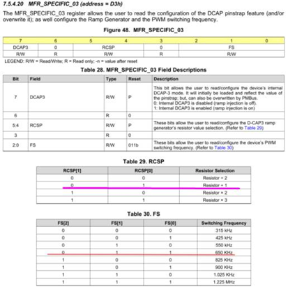
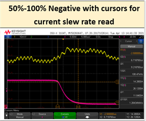
The output voltage has a subharmonic oscillation and the Fsw ripple frequency is around 350kHz. The subharmonic oscillation is~20kHz at 50% load and ~33kHz at 100% load.

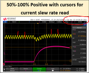
1. Transient from 50% load to 100%load.

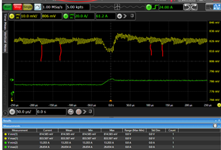
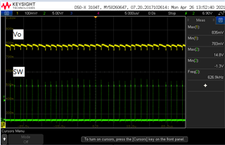
2. Waveform of SW and Vo as below, at 50% load=13.44A:

many thanls

Denny

  • Hi Denny,

    The steady-state waveform of SW and Vo looks as expected. Based on the information you shared, the input Voltage appears to be approximately 15V. Do you have any information regarding the output capacitance, inductor size, output voltage and reference voltage? This information would help us better determine if a stability issue may be seen or if some of the parameters may need adjustment to improve the transient response. A customer schematic in this instance would be helpful if you would be able to provide that as well.

    Regards,

    Alec Biesterfeld

  • Dear Alec

    Sorry the information is not clearly.

    The spec of device : Vin = 12V, Vo = 0.88V, Io = 26.88A

    Inductor is 230nH, out capacitance is 1160uF.

    The schematic as below :

    Many thanks

    Denny

  • Hi Denny,

    After reviewing the schematic nothing appears wrong to me immediately. However the behavior you demonstrated following a load transient step may be indicative of the need for additional output capacitance, lower ESR capacitors, or feed-forward compensation. I will ask some additional team members, but this would be the place to start in troubleshooting the behavior you are seeing. To me, the steady-state waveforms look good, but the transient response is marginal. I will continue to examine the schematic and see if I find any additional things that may explain the behavior. 

  • Hi ,

    Sorry that I will close this post first as there is no further concern . You can re-open it if you have any other question .

    thanks for understanding .

    BRs,

    Young

  • Hi Alec

    Is it any update about this issue?

    Many thanks

    Denny

  • Hi Denny,

    Could you please provide me the data in register MFR_SPECIFIC_03 (address = D3h)? We may need to adjust the compensation settings. I recommend Bit 5 and Bit 4 (RCSP[1] and RCSP[0] respectively) be set to 00b given the parameters of your design. This setting influence the bandwidth of your design and may explain the instability of your supply during a transient event. This can be confirmed by taking a bode analysis of your design as it is currently configured as well.

    Regards,

    Alec Biesterfeld

  • Hi Alec

    Thanks your recommend.

    The customer reply ad below

    Currently, the value of MFR_03=0xD3 is 0x93; i.e., Bit 5 and Bit 4 (RCSP[1] and RCSP[0])=[01]=R%1.

    Later on, we can change it to 0x83 ((RCSP[1] and RCSP[0])=[00]=R%2), and check if there is any improvement.

    Many thanks

    Denny

  • Thanks for the information Denny! Please let me know if you have any further questions following the evaluation!

    Regards,

    Alec Biesterfeld