This thread has been locked.

If you have a related question, please click the "Ask a related question" button in the top right corner. The newly created question will be automatically linked to this question.

BQ25895: BQ charger ICs questions

Part Number: BQ25895
Other Parts Discussed in Thread: BQ25713, , BQ34110, GPCCEDV, BQ25890

Hi E2E,

Good day.

Our customer is designing a battery charger solution using the BQ25895 and BQ25713 and needs your expertise on the device for the following questions: 


"I've started to design a single-cell, Li-Pi battery-powered system. The requirements are listed below:
- Fast charging the battery (I've used bq25895)
-Reading the percentage of battery charge
-Provide the supply of the main board using two approaches:
1. When only the battery exists and the charge is more than 3.7V,
using the Batt. to powering the system.
2. When the charger plugged in and the Batt. is depleted, using the
charger to provide system supply.
The main challenge is here. When I plugin/out the charger in, regardless of the charge state of the battery the Vsys and PMID pin dropped for a while and the system will face troubles. How can I solve this unwanted interrupt in the power line?
-----------------------------------
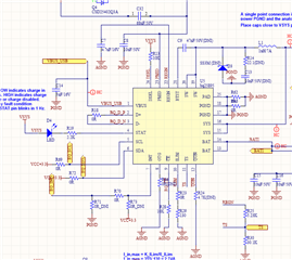
I've designed another version using a 2-cell battery using BQ25713 charger IC, BQ34110 fuel gauge, and BQ296230DSGR protector. I have some questions:
Under-voltage detection:
The BQ25713 discusses "Vbat.Under.Voltage" around 2.55 volts. in the case of using a 2-cell battery is it check any cells separately. In other words, compare each cell to "Vbat.Under.Voltage= 2.55"? what happened if the bat. under-voltage detected? is the BATFET will be deactivated or anything else/more?
If the battery removed(I didn't use battery removal detection and applying '0' to cell_BATPRES pin )can the proper charger (plugged in) provide sufficient voltage on the sw2 or Vsys pin? Can I use the pair of the diode for vbat and vsys/sw to be sure about output voltage, like what designed for the 3.3v regulator on the EVM file?
-How can I find the percentage of battery charge on the BQ34110 fuel gauge?"

Thanks in advance for the help.

Regards,
Carlo

  • Hello Carlo,

    I can help with the bq25895 and bq34110, but I would suggest making other threads for the protector and bq25713 since there are many questions and the protectors are part of a different team.

    For the bq25895 questions, can you share the waveforms of the adaptor being plugged in and un plugged? VSYS, PMID, VBAT, and VBUS would be helpful to see their behavior.

    For the bq34110 you will need to perform some cycles on the batteries following the GPCCEDV tool to calculate the batteries coefficients, then you can read start of charge.

    Sincerely,

    Wyatt Keller

  • Hi Wyatt,

    I just received an update from our customer. Here are the details provided:

    We want to provide stable output (Voltage>3V and Current < 3A(start-up load current)). The system should work in "only-battery-connected-mode", "only-adaptor(Vbus)-connected-mode" and when both are present. Also, we have to use maximum charge current to reduce the charging time of our battery.

    I'm working on BQ25890 And BQ25895 ICs. the first question is here:


    1- The operation should be continuous regardless of the input power provider(BAT, VBUS, or Both). Hope Vsys, PMID(when the adaptor is present) or both will support the expected supply, Please let me know if it will/won't possible.

    2- I've initiate BQ25890-5 as listed below:
    REG# Value
    00 0x30
    01 0x05
    02 0x71
    03 0x30
    04 0x20
    05 0x13
    06 0x5E
    07 0x80
    08 0x03
    09 0x44
    others will set according to default values. Vbus is (5V-3A) or (9V-3A). current LIM. pin pulled down with a 330-ohm resistor and CE pulled down.
    first of all, I've Checked chargeEN bit(REG[4]=1) and charge (fast charge) and REG0C=0x00 all was correct but the battery didn't charge (REG12=0x00).
    at the same situation in another test, Battery starts charging but, after a while, thermal regulation status indicated '1'(4-Leyaer PCB with a heat sink on power pad). After this test, the charge current was zero without any fault!
    I've changed IC, PCB sample board, Input supply and checked all the PCB connections but, there is no reason to know why there are no acceptable responses.

    The BQ25890 was chosen first and we figured out that the Vsys. can't provide load current(3A and more in start-up spikes) we decided to check BQ25895 parallelly. The first question was to know if this single-cell battery charger can meet the project goals or we should switch to a 2 or 3-cell battery charger approach.

    About the second question, both of them cannot charge the battery but the BQ25895 is more important to us, and I reported registers of the BQ25895. I've checked all registers value, all "e2e" same issues and also "8741.BQ2589x_898x_ FAQ" but, nowhere the answer. The CE pin Charge En Bit, REG 0x0B, and REG 0xOC seem to be ok but the charger doesn't charge the battery.
    I also tried this customer (e2e.ti.com/.../bq25895-bq25895-not-charging) experience and REG init, But the result was the same.

    Below is the schematic.

    Looking forward to your further advice. Thank you.

    Regards,
    Carlo

  • Hello Carlo,

    Can you test the same setup and registers with the EVM and see if the issue still occurs? I can try to test on my side with your register settings on our EVM, if you have CE pin pulled low and the CHG_CONFIG = 1 it should begin charge, as long as the BATFET is also enabled.

    I can't follow the link posted, it says page not found. Have you followed the schematic checklist?

    e2e.ti.com/.../faq-bq25890-faq-bq2589x-schematic-review-and-pcb-layout-design-tips

    Sincerely,

    Wyatt Keller

  • Hi Wyatt,

    There is no testing setup available on our end, I will let the customer do the testing with the configuration provided.

    Here is the E2E link, I just removed the closing parenthesis: https://e2e.ti.com/support/power-management-group/power-management/f/power-management-forum/624886/bq25895-bq25895-not-charging

    Regards,
    Carlo

  • Hello Carlo,

    Let us know what the results are from the EVM testing.

    That link also has a lot of good information about when charging is enabled and what can cause there to be no charge. As mentioned in that thread if there's a large load on VSYS the current from VBUS may all be going to VSYS and not charge the battery.

    Sincerely,

    Wyatt Keller

  • Hello Wyatt,

    Here is the response we got from the customer:

    "Unfortunately, I don't have EVM board to test but, every concern has met In PCB design as you mentioned. I'm not sure about BATFET but Vsys voltage is available, is there anything else to check? Every time I check the I2C connection and CHG_CONFIG = 1 and also charging status and the fault register(0x0C) but the charge current still zero.  I have changed IC to another one (same part number) but the results are still the same. What can I do dear?"

    Do you have any other suggestions that our customer can test? Thank you.

    Regards,
    Carlo

  • Hello Carlo,

    Make sure the BATFET is not open, the charge can be enabled in the registers, but if the BATFET is disabled there will be no charge. The charger will supply VSYS from VBUS even if the BATFET is open so that would not be a good indicator unless the BAT voltage and VSYS are the same.

    Charging should occur when:

    1. CE pulled low and CHG_CONFIG = 1
    2. BATFET is on
    3. VSYS does not require all the current
    4. No faults

    Sincerely,

    Wyatt Keller

  • Hello Wyatt,


    Our customer has checked BATFET status and the response is as follows:
    -CE pin =0,
    -Qon pin is 3V.
    -REG09[5]=0
    -No load on Vsys pin

    Here is the init. values:
    REG0 to REG09:
    (0X"30",0X"05",0X"70",0X"10",0X"08",0X"13",0X"5E",0X"81",0X"03",0X"44")
    and read values after connecting Vbus=5V , Host, and Battery:
    REG00 to REG14:
    0x30, 0x05, 0x70, 0x10, 0x08, 0x13, 0x5E, 0x81, 0x03, 0x44, 0x93, 0x76, 0x00, 0x11, 0x3B, 0x3A, 0x4C, 0x97, 0x00, 0x30, 0x3A

    The charge current is still zero.
    I've checked another situation when the host is disconnected and BQ should work in default mode (CE=0 and Qon=3v ) the STAT Pin is low but the multimeter shoes now charging current again.

    The last result was for 5V-5A adaptor and 5v commercial voltage supply which the charge current was zero.
    By using a 9-V 3-A adaptor the charging started, and by changing the input adaptor to 5v the charge current goes back to zero.
    The first question is here? why this situation happened and how can I use a 5V adaptor too?

    After a while when the current of fast charge increase by the host command to 2A with VBAT=3.5V the thermal regulation status indicated '1' (4-Leyaer PCB with a heat sink on power pad and distributed polygons) Is it normal?

    Thank you for the help,

    Regards,
    Carlo

  • Hello Carlo,

    If the default register configuration allows charge then one of the register settings is most likely causing the issue. I do not know all the system specifications to eliminate what may be the issue for some of the settings.

    How are you reading the current? Can you capture the switch node while in this mode along with VBUS, and VBAT?

    Sincerely,

    Wyatt Keller

  • Hello Wyatt,

    Our customer would like to thank you for the assistance.

    They have follow-up concerns and attached is their PCB layout. They also use a hit-sink but when the charger starts charging with a 9V, after a while the thermal regulation bit show '1' and charging stops. According to the customer, he wants to finally use a 5V adaptor and thinks they'll have this issue with a 5V adaptor too.

    8306.TI.pdf

    Regards,
    Carlo

  • Hello Carlo,

    The switch node of their charger is quite large, that may radiate a lot of EMI to the system. Can you ask for the waveform captures I mentioned previously?

    There should be no issue charging the battery when VBAT = 3.5V and VBUS = 5V. I have tested this on my side and it works without the issue reported. If they could verify that with the EVM it does not occur as well on their side we can focus on the hardware design.

    Sincerely,

    Wyatt Keller