This thread has been locked.

If you have a related question, please click the "Ask a related question" button in the top right corner. The newly created question will be automatically linked to this question.

LM5035C / Latched Load Over-Voltage Protection

Guru 29690 points

Hi Team,

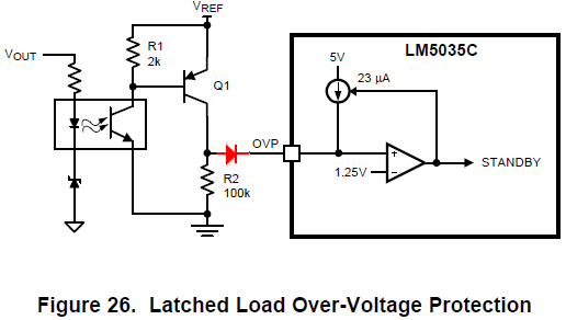
My customer considers to use "Latched Load Over-Voltage Protection" as Figure.26.
He would also like to detect two types of OVP failure by OR-ing connection.
Is it possible to put a diode as the following?

I concern if it can operate "Latched Load Over-Voltage Protection".

Best Regards,
Yaita / Japan disty

  • Hi Yaita,

    I see nothing wrong with using  diodes to form an "or" gate for two parallel OVP circuits. However, you need to be aware of the leakage current that can flow throw the diode even when it is reverse biased. You have to be sure that R2 times the leakage current stays below 1.25 V even at worst case high temperature. For example, if the leakage current out of the OVP pin is 1uA and the reverse leakage current of the diode is 1uA, (the BAT54 has 2 uA leakage current.) then the voltage at R2 is 100 K *1E-6 = 100 mV. So if you have two OVP circuits in parallel you might get 200 mV across R2 due to leakage current. That's okay, but you have to measure leakage current and take this error into account.

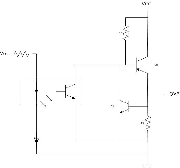
    As far as latching is concerned, IMO this circuit does not latch. As soon as the OVP condition is removed the PWMIC gate drivers turn back on. In order to achieve a latched condition you need  a latching circuit.  I would use a sensitive gate SCR as a pull up. See the circuit above. You can use this discrete, two transistor circuit as a latch. It is described by Robert Kollman in his "Power Tip 38: Simple latch circuit protects power supplies" article. I have used it  before and it worked great. By adding Q2, you get a latch condition whenever Q1 turns on. The voltage across R2 will stay above 0.7Vs and keep Q2 on, which in turn keeps Q1 on. The power from Vref must be removed before the circuit will reset.