This thread has been locked.

If you have a related question, please click the "Ask a related question" button in the top right corner. The newly created question will be automatically linked to this question.

ptd08a006w Inhibit pin problems

Other Parts Discussed in Thread: PTD08A006W

We have a design with four ptd08a006w providing four different supplies. The four ptd08a006w share one inhibit line that is pulled-up via a 10kΩ resistor to 3.3V (generated by the controlling UCD). These are the only five connections to this line. (four modules, one pull-up).

One of our systems has developed a fault after nearly a month in operation in which the inhibit line goes to less than 1.2V, causing all four modules to shut-down. Under this condition I measure from 1.5kΩ to 700Ω to ground (variable depending on condition, see below, but independent of measurement polarity ). On the running system, the inhibit line remains at around 3.33V (depending on the UCD supply, of course; which in this system is around 3.38V).

The fault is intermittent, in the sense that when I probe the INH line with a multimeter that can push up to 1mA into it, the fault will go away (for a day or more) and the impedance to ground would raise to 14kΩ or so. This is a reliable way to get the modules to start again. Measure with the multimeter, wait for the impedance to raise above 10kΩ, then power the system up. A lower-current multimeter would not change the fault condition. We have thoroughly verified the connections, and ensured that there is no solder or flux residue present on them.

I cannot find any documentation regarding the circuitry behind the INH line, and I see no obvious reason for an intermittent fault that gets cleared by the simple fact of measuring it. We have no obvious way to isolate which one of the modules is at fault without removing each module individually. I could simply try to use a smaller value pull-up (e.g., 1kΩ) and hope that it works, but I would like to know what is the root cause of this problem.

  • The inhibit pin input   must be when not used, have about 3.3V.The inhibit pin when low  disables the PTD modules .

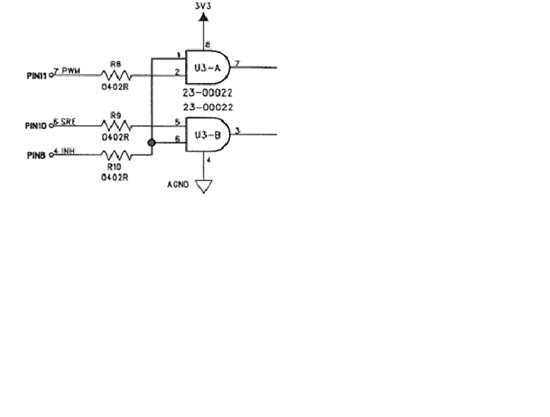
    This input and control is to a dual AND gate IC  which controls the SRE and PWM inputs  from the UCC92XX  to the  PTD08A006. The  AND  gate input has a very high impedance. You state the resistance is about 700 ohms to 1.5k ohms. The 1.2V is  possibly either a open circuit voltage or a PCB host board leakage . Attach a scope probe to monitor the inhibit pin . This  inhibit voltage must be on a DC voltage of about 3.3V.  

    Tom

  • There are only five components on this pin. One 10k resistor to 3.3V, and four PTD08006. This is one board out of ~15, and it is the only one that has shown this problem. I have verified residue and leakage on the PCB and I find none. I have verified component connections and solder joints, and these are as designed. The only possible source of the (intermittent) 1k leakage to GND has to be through one of the modules themselves.

    This particular board worked for more than a month before it started displaying this problem, and even then I can make it reliably start working for a few hours by just applying some current to the pin. I have observed the pin in operation and it is a steady ~3.3V until it fails (which being intermittent has been elusive to capture).

    Can you give me the part number of the AND gate being used, to ascertain its input configuration?

    The module datasheet requests 10kohm to Vdd for one module and you state that this is a high-impedance input, for reliability should I reduce this to ~2,5kohm for four modules in parallel?

    Thanks


  • The AND gate 74LVC08G requires does not load the  input to it. The minimum enable voltage is 2.0V . I suspect the pin are  solder  bridging to  pin 8( Inhibit )  from either  pin 9 or teh PCB host board has a intermittant bridge.