This thread has been locked.

If you have a related question, please click the "Ask a related question" button in the top right corner. The newly created question will be automatically linked to this question.

DCP011515DBP incorrect output

Other Parts Discussed in Thread: DCP011515DB, DCP010505DB

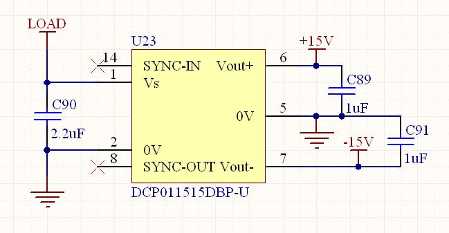
I try to convert 16.5VDC to +15VDC and -15VDC by DCP011515DBP. The circuit is show as below. But the voltage of DCP011515DB's pin 6 and 7 is all 0VDC(very low load). Why?

Help! Thank you!

  • The input power supply 16.5V source must have an current rating of at least 500mA to  1 amp per unit.

    The possible reasons for no output voltage are:

    1. If the input power is current limited and not allowed to be at 15V, then  there will be no output voltage.

    2. The  absolute maximum load is 1W or 33mA per output  voltage rail.  

    3. The capacitors  on both the input and output buses must be ceramic capacitors .

    Tom

  • Hi Tom, Thank you for your tips. I have checked my work:

    1. If the input power is current limited and not allowed to be at 15V, then there will be no output voltage.

    The power is not current limited and is a little above 15VDC (measured by multimeter)

    2. The absolute maximum load is 1W or 33mA per output voltage rail.

     My load is two OPERATIONAL AMPLIFIERS and three iCMOS Switches. The whole load is far less than 1W. I directly connect pin1-power 15V,pin2-GND of power, there are still no output voltage on the pin6 and pin 7.

     3. The capacitors on both the input and output buses must be ceramic capacitors .

    Yes, They are ceramic capacitors.

     Otherwise, I used a DCP010505DB as the same as the figure above. The out voltage is +5.59V and -5.55V, which looks all right. But why a DCP011515DB can't work?

    Another question: DCP011515DB is a isolated DC/DC. But I connect pin2 and pin5 to the same GND. That is not "isolated". Is it all right?

  • Zhuo:

    Thanks for the data.

    1. the input ground pin 2 can be connected to the output ground pin5. Pin 5 can be the ground for the  other components. The sync. pin pin 14 must be open, if not used to sync. the unit to an exteral oscillator.

    questions?

    1. What is the  measured voltage on:

    Pin 1 to pin 2

    Pin5 to to pin 6 and pin 5 to pin 7. Is the 1uf  ceramic capacitors on each Vout bus to ground at least a 25 to 50V ceramic. Unloaded Vout bus  can have as much as 30V (±) on each bus unloaded.

    Tom

  • Hi Tom

      It's kind of you! Thank you for you help!

      The  Voltage is:

    Pin 1 to 2:  +15.5V

    Pin5 to 6:  +0.0V

    Pin5 to 7:  -0.0V

    The 1uf  ceramic capacitors on each Vout is 0603 Y5V. I'll replace them to bigger one to have a try.


  • Hi Tom

      I replaced the 1uF and 2.2uF ceramic capacitors from 0603 to 1206. But the output is still incorrect. The output can even reach +35V and -35V when there is no load. Is this correct?

  • Zhou:

    I revewed all e-mail. 

    I recommend the removal of all output loads from this converter.  Physically measure the voltages at the pins of the  converter:

    1. Pin 1(Vs) to Pin2 (input ground)

    2. Pin2 to pin 14 input sync. pin If no voltage is present on this  pin 14 then evaluate for possible ground connection

    3. If pin 14 has voltage, then

    Measure voltage between pin 5(OVout) to pin 6

    measure voltage at pin 8 Sync out pin to ground pin 5.

    Sent me results of these tests.

    Thanks

    Tom