This thread has been locked.

If you have a related question, please click the "Ask a related question" button in the top right corner. The newly created question will be automatically linked to this question.

LMZ14203H Inverting Design

Other Parts Discussed in Thread: LMZ14203H, TPS84259, LM5576, LMZ14201H, LMZ14202, LMZ14203, LMZ14202H, LMZ34002, LMZ35003

Hi,

I'm using a LMZ14203H Simple Switcher to generate a 15V output voltage for an ADC. But this ADC needs a voltage of -15V too, and I want to use this same Simple Switcher to generate this voltage, because I have some of them in stock.

I used the SNVA556 and AN-2027 as reference and tried to simulate the circuit on PSpice, using the exactly circuit presented on the references. But the output stayed on 0V with a little oscillation between - 2mV and +2mV. I think this may be a limitation in PSpice model.

Has anyone simulated or tested this design? It really works?

Thanks.

  • We have tested the inverting configuration in An-2027. I have not personnally tested 15V, but there should be no problem with it.  The easiest way to test it is to order a stock evaluation LMZ14203H board.  Connect the board as shown in the AN and you should get -12Vout. Remember to follow the ap note guidleines for level shifting the EN pin. Also remember that most electronic loads turn into diode shorts if they see a negative voltage and to swap the leads accordingly.

    Remember that in the inverting configuration the switch stress is Vin + |Vout| so the maximum input voltage is 42-15 = 27V.  In otherwords don't use higher than a 24VIN rail.

    Regards,

    Marc


  • Thank you Marc,

    I'm in Brazil, so it's faster I develop a prototype to test than order an evaluation board. I'll test with -15V, but I wasn't remembered of the switch stress, thanks for remember. Because of this I won't can use this simple switcher, the input voltage available for my circuit can be between 24 and 32 volts.

  • The TPS84259 would also be a good candidate for another part to look at.  It is a positive to negative converter at two amps.

    You could also try the LM5576 in an inverting configuration.  It is a 75 volt part and can easily handle the voltages you are looking at.

    Regards,

    Marc


  • I'll see these regulators Marc, thank you.

  • Hi, Marc:

    Will LMZ14201H work in the same inverting configuration to have a -7.5V voltage?

    Thanks.

    -Wenwei

  • Yes, the LMZ14201H will work in the inverting configuration for -7.5V.  This will still keep the max switch stress under 42V when using a 32v max Vin.


    Regards,

    Marc


  • I also want to create a +/- 15V rail for my op-amps. I am starting to look at the LMZ1420X line of products. It seems like above it was recommended to use the LMZ14203 for this however the data sheet says the max output voltage is 7V. So I started looking into the LMZ14202 which has a higher output voltage of 5-30Volts. 

    Also what can the expected current output derating be when configuring for -15V from the standard 2A version?

    I need to drive about 1A +/-15V peak and about 500mA continuous, which chip would you recommend.

    Thanks,

    Brandon

  • The LMZ14202H can be used depending on your input voltage.

    The current in an inverting design is the input current + the output current.

    For example.  24V to -15V at 1 A.

    Input current is 1A *15/24 = .625 A

    Output current is 1 A

    Efficiency is say 90%

    so total switch current is 1+ 0.625 / .9 = 1.8A  This is the number you compare to the current limit of the part.  Since this is a two amp part you could use it for this design but it will change with input voltage.


    Regards,

    Marc

  • I will be using 24V as my input voltage so this seems to work just fine, thanks for the explanation.

    Can I use the LMZ14203 to create the +/- 15V? After posting my last message I checked the LMZ14202 datasheet and it says the same thing as the LMZ14203.

    LMZ14202H

    EN, FB, SS to GND              -0.3V to 7V

    LMZ14203

    EN, FB, SS to GND               -0.3V to 7V

  • Hi Brandon,

    Also look at LMZ34002 for 24V to -15V and LMZ35003 for 24V to 15V.

  • Thanks for the tip on the LMZ34002 and 3, just ordered some of the eval kits to test them out.

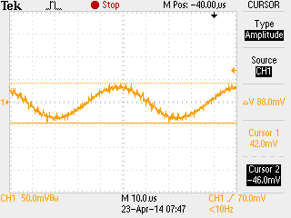
    I also used this app note http://www.ti.com/lit/an/snva425a/snva425a.pdf to create a -15V and -5V rail using the LMZ14202H. However I am getting very large output ripple on the negative rail when i load it down to about 1A. Any idea what may be causing this?

    -15V @ 1A

    -5V @ 1A

    ?