This thread has been locked.

If you have a related question, please click the "Ask a related question" button in the top right corner. The newly created question will be automatically linked to this question.

LM5017 failling

Other Parts Discussed in Thread: LM5017

Hello,

Two LM5017 have failed so far. It doesn't always happens but when it does part of the IC burn out. The Vin is around 60V and the output is 12V. That 12V is used to power some 5V IC and MOSFET gate drivers for a SIX phase motor controller. I had monitored the 12V current consumption and I got an average value of about 25 mA. I know that there are some pick current when the MOSFET gate is driven (about 1.2 A since I use a 10 ohm resistor between the driver and the gate). But I use very well sized low size and bootstrap capacitors for each drivers so I think the MOSFET gate peak current shouldn't be an issue. 

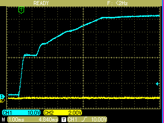
I think the problem could be related to the big size capacitors on the 12V side and the LM5017 start-up. Actually I use a 10 uF bootstrap capacitor and a 100 uF low side capacitor (maybe quite too large) for every of the six drivers and two 22 uF capacitors on the LM5017 Vout side.

I am thinking about adding the soft start feature to the LM5017 design. Could that be the solution to the problem?

Many thanks in advance.

Best Regards.

  • Hi Ismail,

    The picture is not clear in my head. WOuld it be possible to share some kind of schematic or block diagram. Are you using LM5017 is a buck or FlyBuck topology?

    Thanks and regards,

    Vijay

  • Hello Vijay,

    Thanks for the replay and sorry for any confusion. I use the LM5017 as a buck converter as you can see in the first attached document. The second attached document shows the main use of the 12V output from the buck converter, apart of supplying power to the 5V line. That second schematic is replicated twice for the same board so that 12V line supply power to 6 IR2110 MOSFET Gate Drivers. So the total capacitance in the 12V side is quite big and I wonder whether that would be an issue at start up so a soft start is needed. 

    Some pick currents are present to charge the MOSFET gate but I believe that shouldn't be an issue for the buck converter because of the large capacitor placed on each driver. 

    Best regards.

    3276.DCDC_V31.pdf5584.OUTA_MOSFET_V31.pdf

  • Hi Ismael,

    What is the saturation current of the inductor you are using?


  • Does it always fail during startup?

  • Hi Vijay,

    The inductor used is in this link http://es.mouser.com/ProductDetail/Bourns/SRR1260-391K/?qs=sGAEpiMZZMsg%252by3WlYCkU7%252bI2Fr4H6MuAl%2f8KfAFVT0%3d. It's a 390 uH inductor with 1A saturation current. 

    The LM5017 has always failed just when starting to switch the MOSFETs after powering up ( at least is when I see the LM5017 burning up). But it doesn't always happen at all in fact I have been testing the board already a few weeks and two LM5017 have failed so far. I understand that with this information it's difficult to know the source of the problem. But at least I would like someone confirms if I am right when I say that the LM5017 buck converter and the capacitors placed on each MOSFET driver are enough to supply the peak currents to charge the MOSFET gate. The switching frequency is about 16 KHz.

    I attach a file with the board PCB design of the buck converter side.

    Regards.

    6758.DC DC board.pdf

  • Hi Ismael,

    LM5017 has short circuit protection built in. So as long as the inductor does not saturate it should protect itself even if overloaded. I think it would help to trigger on a failure condition (observe IL, VIN). Is there a particular reason to use 390uH inductor. I am wondering if the failure happens if you switch to 220uH inductor in the same series which has higher ISAT rating.

    Do you think the converter is starting with discharged outupt or the output is already pre-charged when this failed startup happens?

    Also do you think your power supply may be overshooting (above 100V) when powering up?

  • Hi Vijay,

    As I said in the previous post the LM5017 failed just two times along the last few weeks of tests. So I don’t know which conditions need to be stablish to trigger on a failure.
    The inductor value was increased because I thought it would be better to have lower inductor ripple current, but I will give a chance and switch the inductor to a 220 uH value.

    I know for sure that on the second failure the 12V output was discharged. The oscilloscope doesn't show any ringing on the Vin at power up (a file of the oscilloscope output is attached). Since the large input capacitors in the Vin as you can see on the second schematic ( 8 x 680 uF ) I have start using a precharge circuit from the last few days to reduce the huge initial pick current and also avoid any ringing.

    I hope these changes are sufficient to prevent further failures. While I have concerns about the high capacitance in the 12V side and high energy demand is needed at start up so therefore a soft start in the buck converter should be necessary. What do you think about it?

    Best regards.


  • Hi Ismael,

    Did you manage to fix this problem.  If not did you find an alternative solution?

    thanks in advance

    Paul