This thread has been locked.

If you have a related question, please click the "Ask a related question" button in the top right corner. The newly created question will be automatically linked to this question.

LM25088 whining

Other Parts Discussed in Thread: LM25088, LM5088

Hello,

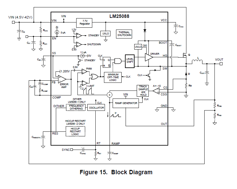
I have designed, using WEBENCH tool, a DC/DC which implements the LM25088. 


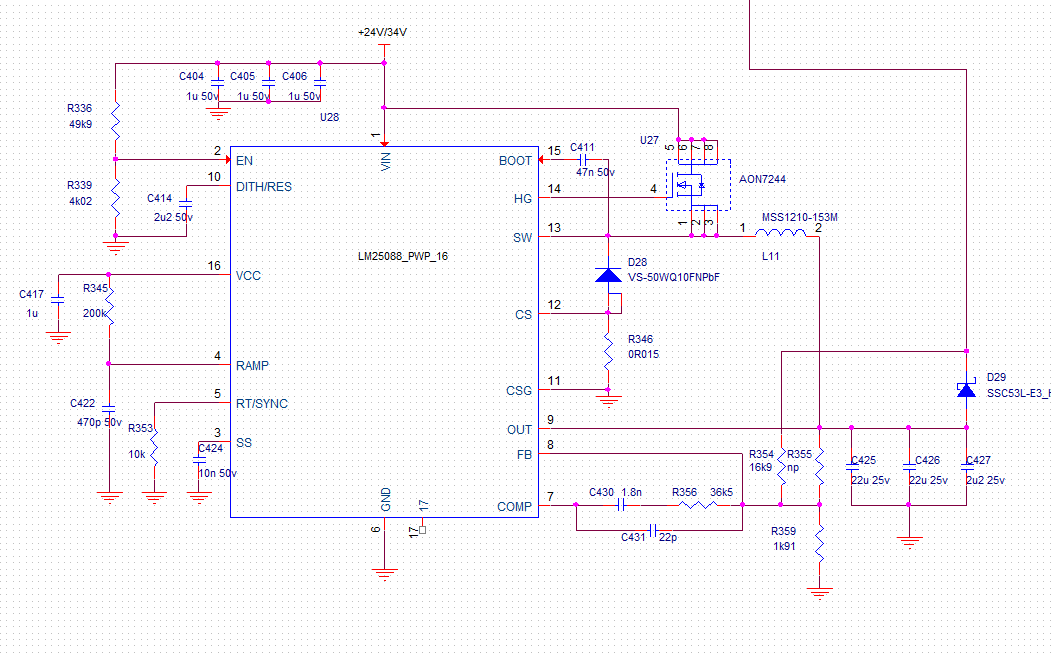
The input voltage is from 24 to 34v, and the output is at 12v. When I designed it I did it for 3 or 4 amps, now I found out that 1.5A will be enough, yet I cannot see it working correctly. With no load the voltage is reasonably good (11.85v), but when I apply some load and the current rises to 500mA, output voltage drops to 10v and the inductor starts to 'whine' at a few kHz. This is what I see at the HP pin with a 500mA load:

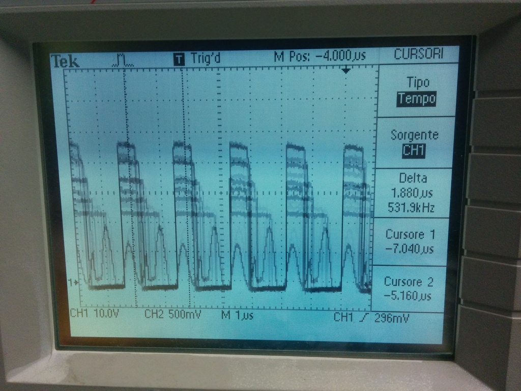
The following image is at a slower time base: what you see is the envelope of the HG signal, and therefore the reason of the whining:

The only mistake I can account for is that we forgot to connect the thermal pad to ground, but I solved the problem by soldering a thin copper foil underneath the package and then connecting it to ground. Neverthless, no difference in the behaviour.

As I said, I designed this circuit some months ago, now I did it again and this time WEBENCH gave me different results, I do not know why. I set up input voltage from 20 to 40v, output voltage 12v at 1.5A or 4A (a few differences). Neverthless, I simulated my values and things appear to be well: at least it does not appear to be unstable:

Can anyone help? I am out of ideas...

Thanks,

Paolo.

  • Hi Paolo

    I guess a dummy resistor load at the output (#2 pin of L11) will help.

    The value of the dummy resistor should be small enough to keep HG switching at every cycles without any pulse skipping 

    Also, adding an additional boot diode from VCC to BOOT and/or increasing C411 might help.

    Regards,

  • Hi Paolo

    Or you can try the way described in this Application Report. Please refer Figure 4. Boot Capacitor Regulation in LM25007 Constant-On-Time (COT) Converter (Rev. A)

    Regards,

  • Hi Eric,

    thanks for your reply, I can try the solutions you suggest, however I do not think this is my case... As you can read in my post, the problem becomes increasingly evident as I increase the current drawn at the output. The waveforms you see are taken with a 500mA load! It seems there is some sort of self-oscillation involved, even if I cannot see the cause for it... according to the Bode plots, it should be stable... do you agree?

    Thanks, best regards

    Paolo.

  • Hi Paolo

    There is something you can try. Sorry for my misunderstanding.

    1. I see a phase drop around 500 Hz to 5 kHz at light load. If the symptom was caused by this phase drop, you may be able to see an improvement by increasing Ccomp to about 3.9nF
    2. Dithering might cause this symptom. If you are using dithering version of LM5088. short DITHER pin to ground and see any improvement
    3. Short D29 diode and see any improvement.

    Regards,

  • UPDATE: I have analyzed the component block diagram in the datasheet:

    I was strongly convinced that there was a self oscillation problem in the compensation loop, and, looking at the diagram, I wondered: if the FB pin is the inverting input of the error amp, why not try to close it to the output? 

    So, I decided to bypass the filter. I removed the CHF and replaced it with a short. Result: no more oscillation. But no more regulation, too...

    Neverthless, I believe that my test stated that there IS a self-oscillation problem! Question is: why? And: how to solve it and make sure it does not happen again?

    What do you think?  

    Thanks, regards

    Paolo.

  • HI

    If you see an improvement by changing compensation component. Please try item 1 and 2 in my previous post.

    Regards,


  • Hi Eric,

    no, I have the -2 version.

    I have changed the capacitor as you suggest ( I added 2.7n in parallel, total of 4.5nF), little change. The device regulates better, but it is still whining.

    What I do not understand is why the oscillation is modulating the HG pin (see pictures in the first post), but, hey, an oscillation is unforseeable by definition... I even added a few ohms in series to the gate (in the past it helped in other cases), but still no luck... :-(

    I am suprised that such a widespread component is giving me all these headaches. I am afraid that, unless you or anyone else can give me a hint about how to solve the problem, I will be forced to abandon this solution and find something less critical...

    Thanks, regards

    Paolo.

  • Hi Paolo

    Since your issue is very complex and critical. I think it is better for you to contact your local FAE and send me your board through your local FAE.  (I am Eric Lee). I would like to check your board on the bench.

    About your question, HG-GND voltage oscillates if SW node oscillates. This is because LM5088 controls HG-SW voltage.

    Regards,

  • Hi Eric,

    yesterday evening I found the reason of the malfunction. The point is that the 24v arrives to the regulator through a complex series of inductors and capacitors (it is extracted from a RF coaxial cable), and apparently they somehow cause the oscillation. I first disconnected everything from the controller, applying the voltage directly to pin1, and all was fine; then I reconnected the LC network and the oscillation resumed. So, I increased the input capacitance by adding a 22uF tantalum capacitor and I finally got a clean output without oscillation. Apparently, 3uF were to little input capacitance in my case.

    Just to let you now in case you need it for the future!

    Thanks for your help, best regards

    Paolo.

  • Hi Paolo

    Thank you very much for your feedback. Next time - if any - please post your full schematic. The issue is on the hidden side frequently. 

    Regads,

    Eric