This thread has been locked.

If you have a related question, please click the "Ask a related question" button in the top right corner. The newly created question will be automatically linked to this question.

TPS23753A Question about SLVA305C

Other Parts Discussed in Thread: TPS23753, TLV431, TLV431A

Hello,

Please answer following questions about “SLVA305A Designing with the TPS23753 Powered-Device and Power Supply Controller” application note from customer.


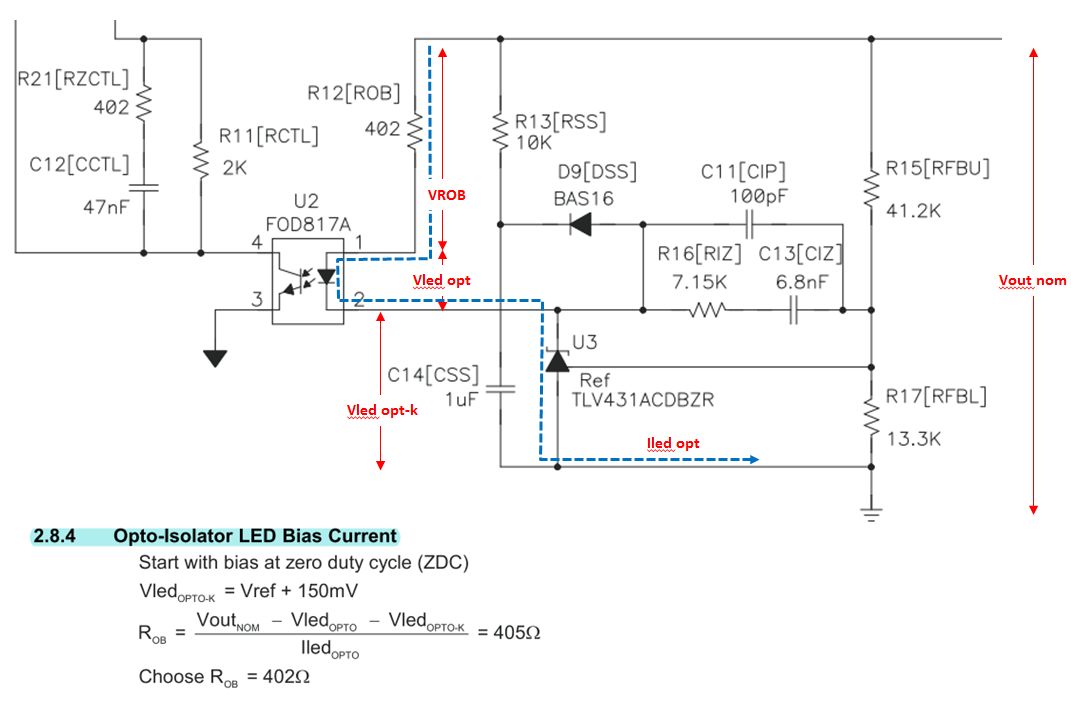
-P12, 2.8.4 Opto-Isolator LED Bias Current

Please advise what is the “150mV” of following equation.


  Vled opto-k = Vref + 150mV


Best Regards.

  • Hello, thanks for the feedback.

    I should have mentioned that the 150mV factor is simply some arbitrary margin above the internal reference voltage of the TLV431.

  • Hello Eric-san,

    Thank you for your answer.

    But I can’t understand that 150mV factor is simply some arbitrary margin.


    Pleas answer additional following question about Vled opto-k.

    Please refer following figure that my understanding is added.


    Q1:

    I think “Vout nom – Vled opto – Vled opto-k” in chapter 2.8.4 ROB equation is voltage drop of ROB and Vled opto-k is voltage drop of TLV431 Cathode to Anode.

    Please answer if my understanding is correct and Vled opto-k is voltage drop of TLV431.


    Q2:

    My understanding of TLV431is that VREF to Anode Voltage is 1.24V but Cathode to Anode voltage is differ form VREF to Anode Voltage.

    Please advise why Vled opto-k is calculated from Vref + 150mV.

    Best Regards.

  • The main objective of this section is to choose Rob based on the target LED bias current. For the shunt regulator (TLV431), Vk = Vcc for the device and Vk-minimum = Vref (see first two feature bullets in the TLV431A DS, SLVS139U)

    FEATURES

    • Low-Voltage Operation, VREF = 1.24 V

    • Adjustable Output Voltage, VO = VREF to 6 V

    In the design app note, you can set Vled-opto-k =Vref if you want to but I had chosen not to operate the shunt regulator all the way down to Vref and as such added 150mV.

  • Hello Eric-san,

    Thank you for your answer.

    Best Regards.

  • Hi Eric,

    In section 2.8.3 (slva305c app note), the LED current is chosen to be 1-2mA. What would be the "concern" if the LED current is lower than 1mA? 

    Thanks,

    Philip

  • Hi Philip,

    Lower than 1mA may create some instability in the converter as it will affect the loop. I recommend sticking to the recommendations in the app note, or even increase the bias currents up to 5mA like in some of our new reference designs.

    In addition, it may be good to take a look at TI Designs which help you find a known working poe pd reference design based on your power requirements.
    www.ti.com/.../refdesignsearchresults.tsp

    Regards,
    Darwin