This thread has been locked.

If you have a related question, please click the "Ask a related question" button in the top right corner. The newly created question will be automatically linked to this question.

LM22674QMR 5.0 problem

Other Parts Discussed in Thread: LM22674

Hi,

I have an issue with LM22674 QMR 5.0.  I have followed the guide by Webench to design the circuit similar to the below: but design for Vin is 14V and Vo is 9V. Rfb1 and 2 at 432R and 330R .

However the first issue I got was that the Vout was about 2V and Vfb is about 1V. I also removed Rfb1 and Rfb2 to check Vfb but it showed 0V. What could likely be the problem ?

Thanks.

  • Hi Koh,

    Did you use Webench to create your design?


    I checked the math and I believe 2V is expected. The equation for determining the resistor values is on page 12 of the datasheet. Translating to Rfb1 and Rfb2 it would be:

    Vout = (Rfb2/Rfb1 + 1) * 1.285 = (330/432 + 1) * 1.285 = 2.27V


    Following the design procedure on page 12, you would choose resistors as follows:

    Use Rfb1 = 1k as a starting point. Then determine R2:

    Rfb2 = (Vout/1.285 - 1) * Rfb1 = (9V/1.285 - 1) * 1k = ~6k.

    Thus you can scale this to any factor in order to fit commong resistor values (though try to keep the sum under 10k for stability reasons).

    For example, depending on how sensitive your load is, you can use 1k and 6.2k which would give ~9.25V.


    Try these resistor values and let me know if you run into other issues.

    Thanks,

    Alex


  • Hi Alex,

    Yes. Used webench for the design. Will try out the suggested resistors value.

    The question I have is that the Vfb pin 4 should be 5V as I'm using the 5.0 type ( based on datasheet) but I am not getting that value(even when I have disconnected the res divider). And lets say I decided instead to use the 5V from Vfb and connect directly to Vout but because the Vfb is itself not of right value, I can't change the design.

    Thanks for your prompt reply.

    Wei Chong

  • Hi Wei Chong,

    I did not realize you were using the -5.0 version. The resistor values you chose should give you ~9V.

    Based on how the device is behaving, it seems like you may be using the adj version and not truly a -5.0 version.


    As you mentioned, try the suggested resistor values and see if you get 9V as a result. This may indicate if it is infact an -adj chip. You can additionally look under a magnifying glass or stereoscope to check the silk-screen on the part.


    Thanks,

    Alex

  • Hi,

    I have changed the resistors values and also checked the IC silkscreen to be -5.0 type but still unable to get 9V( Also, the other resistors combination I used did not change the Vout ). I have also changed the inductor to 100uH. The Vsw is train pulse with peak voltage close to Vin. Ven is about 6.4V.

    Also, I noticed that this chip (circuitry) has caused the overall power consumption of my board to increase. ( When I disabled the chip the current drops significantly). Could faulty/wrong inductor be the reason?

    Many Thanks.

    Wei Chong.


  • Hi Wei Chong,


    You mentioned:

    Koh Wei Chong said:
    Ven is about 6.4V

    Unfortunately this is beyond the Absolute Maximum Ratings specified on page 2 of the datasheet. Because of this, I may fear if the part has been damaged.

    You also mentioned:

    Koh Wei Chong said:
    I noticed that this chip (circuitry) has caused the overall power consumption of my board to increase. ( When I disabled the chip the current drops significantly). Could faulty/wrong inductor be the reason?

    If the part is damaged, this may cause increased power consumption. What was the power consumption before and after turning the device on? What do you have connected at the load?

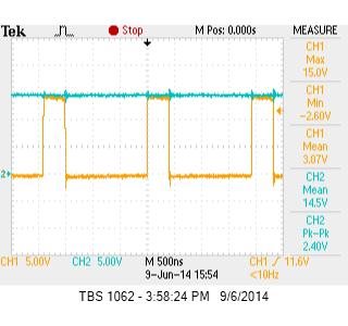
    Can you post your schematic and scope shots of Vin and SW pins (also FB pin and Vout if you have a 4 channel scope)?


    Thanks,

    Alex

  • Hi Alex,

    Please see below. Blue is Vin and yellow is Vsw.


    The schematics.


    Power consumption Before w/o turn on is 1.26W after turn on is 3.78W, without loads.

    Thank you for your assistance.

    Wei Chong

  • Hello,

    Have you swapped out and replaced it with a new part? I don't see any issue with resistor value calculation. When you say you see 0V with feedback resistors removed, are you still connecting FB pin to Vout of your design? If FB is not connected, you have a broken loop.

    Regards,
    Akshay

  • Hi,

    I have changed the IC before. I had removed the resistors and connected the Vfb and Vout together. I got the Vout value of about 1.7V ,  similar to the value at Vfb.

    May I know what might be the cause for Ven to reach its maximum value? 

    Wei Chong

  • Have you checked your connections for any shorts or bad solder joints? The internal zener at EN should conduct to avoid EN seeing more than 6V. But maybe there was a large Vin spike that caused a larger current and damaged the zener. You could try and put in a larger resistor at EN. You could also try using some more bulk input cap. 

    Are you using an EVM to prototype or is this your own board? If this is your own board, would you please send us your board drawings? If you are using your own board, have you tried to port the design on to an EVM? 

    Regards,
    Akshay

  • Hi,

    I noticed this issue when I powered up the board for the very first time. The initial inspection on the board was fine. You are referring to the schematics? The board is our own board. Have not tried it on evm. 

    Wei Chong

  • Hello,

    I am really not sure why the IC is switching to a different voltage. There seems to be some other current path even though you are not loading the design. 3.78W without load seems kinda high for dissipation. Would you please send your layout files? I also would suggest you to check your design on the stock EVM. 

    Regards,
    Akshay