This thread has been locked.

If you have a related question, please click the "Ask a related question" button in the top right corner. The newly created question will be automatically linked to this question.

LM5107bootstrap cap

Other Parts Discussed in Thread: LM5107

Hello

I intend to use the LM5107 in a new design.  The circuit topology is relatively straightforward, or so it seems.

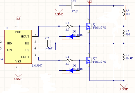
I'm looking to swing the common node (source of Q1, drain of Q2) at low frequency from the DC bias point of ~6V to the top rail 12V and then some time later to the bottom rail AGnd then back to neutral.  See pic below.

The LM5107 is not working as expected.  The high-side fet is not turning on.  The data sheet does not state when/how the bootstrap cap is charged and I suspect that's the root of the issue.  I've checked layout, part values, footprints etc..  When both HIn and LIn are low, both fets are off as expected and the bootstrap cap (HS pin) sees the 6V bias. When the low side FET is on, the cap sees 0V as expected.  The high side FET never turns on and the waveform at HOUT is odd.  The bootstrap cap value is 1uF.  I tried .47uF as well.  The time either FET is 'on' is around 3us, 'off' otherwise.

Any one have any experience with either half-bridge circuits in general or this particular part please??  I don't see why this circuit is so fussy...  

Is it the DC bias point causing issues?

Does the cap charge when the low-side FET is on?  Or, does it simply follow the voltage on the common node?  If that is true, then it should just charge to 12V - 6V = 6V right?  Then, the voltage on the high side gate should be the 6V cap voltage + 12V supply = 18V??  The FET should turn on....

  • Hi TI,

    I'm hoping to get this design to fab as quickly as possible.  Any thoughts?  Any insight you might have would be greatly appreciated.

    Looking at the Block Diagram from the data sheet (below) it appears the bootstrap cap is continuously charged via the internal bootstrap diode.  Based on my circuit config. the HS pin will see +12V (Q1 on), +6V (Both off) or Gnd (Q2 on).  The cap should be charging to either +6V or +12V depending on whether HS is at 6 or 12 volts.  I only turn on the high side FET when the circuit is at steady state meaning HS is sitting at 6V. So HB should be either at 12+6, or 12+12 (minus diode drop).  Should be high enough to turn on Q1.

    I can see a case where the high side FET may not turn on until the low-side FET is turned on charging C2 to ~12V. After that, HB should be sitting between 24 and 18 V...

    What am I not getting here?

    Is there another part I should consider?

    Best Regards,

  • Hello again TI,

    I've simulated the voltages on the HS and HB pins.  See below.

    Red is the HS pin.  Green is HB.  From my previous post, it takes pulling HS low before the cap voltage on HS is correct.  From that point on, HS tracks the voltage on HB as expected.  Seems good to me?   Just before HI goes high, HS is at ~18V.  6V above the rail.  18V is what the high-side gate should see.

    TI I need your help in understanding the LM5107.  

    Please respond.  It's unclear to me why I haven't heard any feedback.

    Thanks in advance.

  • Regretfully, I didn't proof my post before sending.  HS and HB were swapped in a few cases.

    Below is correct.  Changes made from previous are in bold txt.

    Thx. 

    Red is the HS pin.  Green is HB.  From my previous post, it takes pulling HS low before the cap voltage on HB is correct.  From that point on, HB tracks the voltage on HS as expected.  Seems good to me?   Just before HI goes high, HB is at ~18V.  6V above the rail.  18V is what the high-side gate should see.

  • Can I ask you about your application?  You have posted to the non-isolated dc/dc converter forum.  Usually the circuits will be buck or boost converters.  Maybe we need to move this to another forum.

  • Hi John,

    Thank you for responding.  I went to TI directly with my question and they sent me to the E2E forum.  I did a search for LM5107 and all hits were in the DC/DC conv. forum so that's were I started.

    Anyway, I'm using the part in a somewhat non-conventional manner.  It will be used in the front end telemetry system where I need to swing a AC coupled line from Vcc to Gnd.  The part will serve me very well if I can get it to work.  I need someone at TI who is familiar with the part.  The simulations that I've done suggest it should work.

    I don't know how to move the thread to another form If you think that will serve me better.

    Thank you again,