


Hello
I intend to use the LM5107 in a new design. The circuit topology is relatively straightforward, or so it seems.
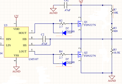
I'm looking to swing the common node (source of Q1, drain of Q2) at low frequency from the DC bias point of ~6V to the top rail 12V and then some time later to the bottom rail AGnd then Q1&Q2 both off, common node swings back to SS of 6V. See circuit below.
The LM5107 is not working as expected. The high-side FET is not turning on.
Any one out there have any experience with either half-bridge circuits in general or the LM5107 part please?? I don't see why this circuit is so fussy...
Is it the DC bias point causing issues?
UPDATE #1
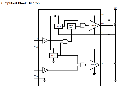
Looking at the Block Diagram from the data sheet (below) it appears the bootstrap cap is continuously charged via the internal bootstrap diode. Based on my circuit config. the HS pin will see +12V (Q1 on), +6V (Both off) or Gnd (Q2 on). The cap should be charging to either +6V or +12V depending on whether HS is pulled high or low. I only turn on the high side FET when the circuit is at SS meaning HS is sitting at 6V. So HB should be either at 12+6, or 12+12 (minus diode drop). Should be high enough to turn on Q1.
I can see a case where the high side FET may not turn on until the low-side FET is turned on charging C2 to ~12V. After that, HB should be sitting at either 18V or 24V.
What am I not getting here?
Is there another part I should consider?
UPDATE #2:
I've simulated the voltages on the HS and HB pins. See below.
Red is the HS pin. Green is HB. From my previous post, it takes pulling HS low before the cap voltage on HB is correct. From that point on, HB tracks the voltage on HS as expected. Seems good to me? Just before HI goes high, HB is at ~18V. 6V above the rail. 18V is what the high-side gate sees I believe.
TI I need your help in understanding the LM5107.
Thanks in advance.


