This thread has been locked.

If you have a related question, please click the "Ask a related question" button in the top right corner. The newly created question will be automatically linked to this question.

LMZ14202H high output ripple

Other Parts Discussed in Thread: LMZ14202H

hello everyone,


i'm facing with very annoying ripple problem.

I have two LMZ14202H modules in my circuit design, both of them gets 28v input.

one is configured for 12v, and the second for 9v


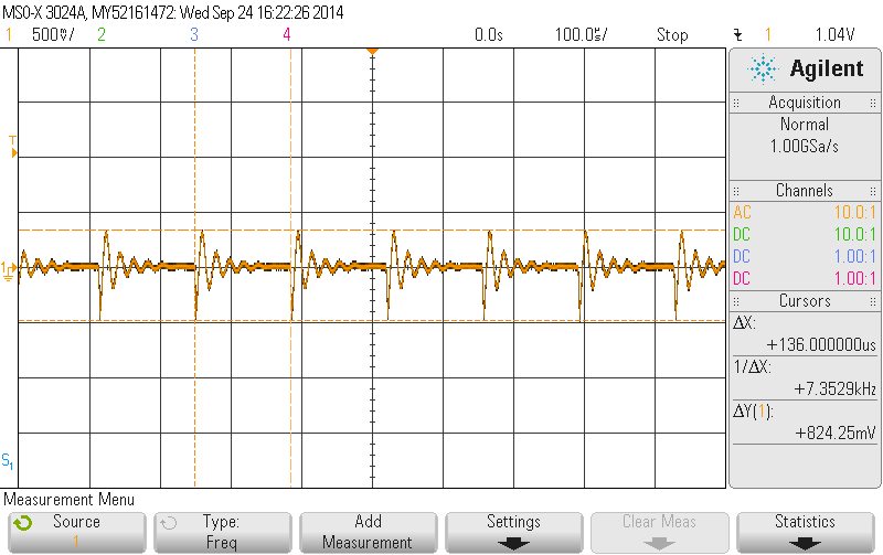
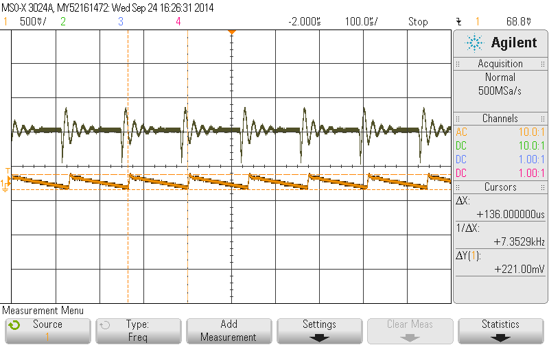
when I measure the Vin and Vout  DC characterization the results are ok

but, for AC I'm facing with very high ripple voltage (without load and with load of 0.5A).

I tried to fix this problem by:


1) adding more capacitance in the input and the output.
2) wire the GND from the input and output capacitance directly to pin 4-GND

3) changing the Cff cap for 0.018uF


4) adding 2x10uF with 2ohm res in parallel to the input capacitor (dumping circuit)

none of the actions that I mentioned above fixed the problem.


important to say:


1) this problem occurred in both modules.


2) I followed the exact measuring guide ( in this link: http://e2e.ti.com/support/power_management/simple_switcher/w/simple_switcher_wiki/2243.understanding-measuring-and-reducing-output-voltage-ripple.aspx)


3) this circuit designed exactly as in the application note of the datasheet


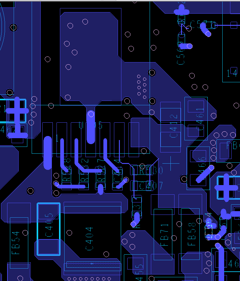
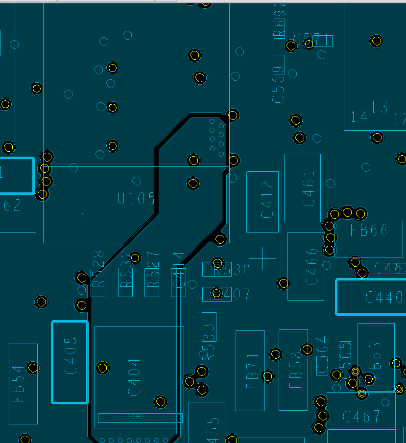
attached to this post the scope waveform, the DSN file and photos of the layout.

Please I need your help to fix this.


Best

3823.LMZ14202H.rar

  • Hi Gil,

    Just to Clarify.  You have two waveforms of the output voltage.  At what load current is each taken?

    Also can you send me the a bom showing the input and output capacitors that you used?

    Regards,

    Marc

  • Hi Marc

    Thank you for your quick answer

    the waveform was taken under load of 0.05A@12v

    but as I mentioned earlier I have tested this circuit under no load, load of 0.5A and 0.05A and the ripples are more or less the same

    regarding to the BOM:

    input caps:

    C404 => C5750X7S2A106M230KB - TDK 10uF 100v X7S

    C405 => CGA5L2X7R2A105K160AA - TDK 1uF 100v X7R

    output caps:

    C412 => 20TQC47MYFT - Panasonic 47uF 20v 55mOhm TAN 

    C461 => 0805B104K500CT - Walsin 0.1uF 50v X7R

    Best,

    Gil

  • Hi Gil,

    I talked with the application engineer for that part.  He said that when the part enters discontinuous conduction mode.  That is when the inductor current reaches zero, the frequency of the part will lower.  This will improve efficiency but it has the side effect of increasing the output voltage ripple.

    Looking at your output capacitors.  Your primary capacitor C412 has an esr of 55mOhms.  This will dominate the output voltage ripple at light loads.

    Try doubling up this capacitor just to check if this lowers the ripple.  If that works than you will want to look for an alternative with less esr.

    I did a quick check and found the Panasonic part below.  It has roughly half the esr but is of course larger. Cost is a little lower


    Let me know if that helps.

    Regards,

    Marc


  • Hi Marc,

    Thank you for your help, I think I solved the problem.

    you can see in the schematics that that Ron was connected to GND accidentally instead to Vin.

    re-soldering this resistor to Vin solved the problem.

    now I measure 50mV approximately at the Vin and Vout.

    Thank you.

    Best

    Gil