This thread has been locked.

If you have a related question, please click the "Ask a related question" button in the top right corner. The newly created question will be automatically linked to this question.

LM25066IA VDD power source other than VIN

Other Parts Discussed in Thread: LM25066IA, LM25066

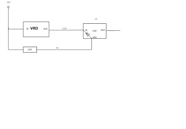
I would like to able to access the LM25066IA via the SMBus before VIN is present. Can I connect VDD to a 3.3V supply which will be available before VIN is up on the device? Or alternatively to VDD of another LM25066IA which will already be powered up

  • Hi Spencer,


    Yes the Vdd can be back-driven to keep the LM25066IA available for communication via PMBus/SMBus before VIN is present.


    We would recommend the external supply to be tapped in through a diode (either small signal or schottky diode such as a BAT54). However, a 3.3V supply through the BAT54 would drive the Vdd pin with ~2.9V (3.3V - a 0.4V drop for the schottky).


    I am checking with our design team to see if we have characterization data for the UVLO of the Vdd.


    Ideally, a 4V supply (this may be rare, but should you have one available) through a BAT54 would be the most reliable solution.


    Thanks!

    Alex

  • Hi Alex,
    Thanks for the information. Is there enough current available out of the VDD pin to power up a second device? I have one device with VIN already powered up with 12v, the other device has a 3V3 VIN but this is not available when I might need to program it. I could wire the VDD pins together if there is enough current from the first device.
    From the datasheet it looks only 5mA? is required on VDD but the on chip LDO can supply 25mA, so there should be enough to power two devices. Would I still need the schottky diode?
    I will have and look and see what I have got available, 4V is unlikely. I could put on an LDO to power up these devices
    Spencer
  • Hi Spencer,

    The LM25066 Vdd will current limit at 25mA. The LM25066 itself will draw up to 8mA from this Vdd regulator, and there is headroom for it to serve as a pull-up for other circuitry (such as a pull-up for PGD, ADR pins, CL/CB, etc), but it isn't meant to power other circuitry such as another IC. The schottky diode was recommended to prevent power coming out of the Vdd pin and prevent the chance of current limitiing the internal LDO.

    I understand 4V is unlikely. A 5V source through a small signal diode can work too, the only downside to that is since the Vdd regulates to a minimum 4.3V, this can cause the 5V source to overdrive the internal LDO during normal operation. This is still ok, but then any noise on the 5V source will make noise internal to the IC (which depending on the severity, it can affect accuracy or in extreme cases I guess it can cause misbehavior of the IC - we haven't looked into this).

    Thanks,
    Alex
  • Hi Alex,

    It is not to difficult to add a 4V supply which will come up before the 3.3V VIN.

    I will be using the 4V rail to power 3 LM25066 so presumably I should supply this power through a separate diode for each device. Should arrange the output voltage of this regulator to >4V provide 4V at  Vdd after the diode drop?

    Spencer


  • Hi Spencer,

    4V should be fine, and yes, going through a separate diode for each device would be preferred in order to prevent IC's from backfeeding other IC's.

    The reason we suggest 4V instead of >4V is to prevent overdriving the LM25066's internal LDO. The LM25066's Vdd regulates to 4.3V (min) -5.0V (max), so by using a 4V source - diode drop, the voltage will always be below the LM25066's internal LDO output.

    Overdriving the LDO should be ok, but keeping it below would be preferred.

    Thanks,
    Alex
  • Hi Alex,

    I have implemented a regulator which provides 4V through a diode to VDD Pin 4 on the LM25066. This voltage unfortunately seems to leak out on to the 3V3 input to the ECB through the device itself on either pin 14 or 15. I have 200ohm pull down on the input, so it is able to drive a few ma.

    Do you think this possible?

    Thanks

    Spencer 

  • Hi Spencer,

    I spoke with our systems engineer and we believe this would be leaking through the body diode of the internal LDO regulator. Here is a simplified diagram:

    So unfortunately, it seems that this leakage cannot be avoided. For the 12V design, the UV will hold off the MOSFET, but for the 3.3V design, the MOSFET can switch on.

    You mentioned the need to program when VIN is not present. If this is the criteria, then I guess this scheme of backfeeding the Vdd for a 3.3V solution may not work due to not holding off the MOSFET from UVLO.

    If you have an MCU which can detect when the 3.3V is plugged in or not, then this simpler solution may work instead:

    Essentially you can utilize an NFET along with the UV (for an active low EN signal) or the OV (for an active high EN signal) in order hold off the external MOSFET until the MCU drives the EN to turn on.

    This will allow you to program the device before powering up the loads. However, this solution requires VIN present in order to program.

    Thanks,

    Alex

  • Hi Alex,

    Thanks for the explanation, I wanted make sure that the ECB was the source of the back fed voltage.

    If there is no damage to the ECB with this arrangement, I will probably leave it as it is.The output is already held off with a MOSFET as you have drawn above. The 3V3 input rail only runs between the regulator and 3 ECB's, so I don't think it should be a problem.

    As you say if we want to pre-program the ECB we have no choice.

    Spencer

  • Alex,

    I think we may have another problem; when the voltage regulator turns on,  the 3V3 input rail to the ECB goes down to 0V so until the rail come up there will 4v across the diode in the ECB. Is this likely to damage the ECB?

    Spencer

  • Hi Spencer,

    I'm unfamiliar with the "ECB" you are mentioning. Can you describe it a bit more?

    Overall is it possible in your system to hold off the the LM25066 by the EN pin, wait for VIN to rise, program the LM25066, then let go of the EN signal and allow the hot swap to turn on (without the need to drive 4V to the LM25066 Vdd?) If possible, this would be the cleanest solution and most straightforward solution.

    Thanks!

    Alex

  • Hi Alex,

    Sorry ECB=LM25066

    It would be best to do it as above but the SW guys like to program the LM20566 at the same time as the 3.3V VR, at this time the 3V3 is not up.

    Hope you can see the picture

    Spencer

  • Hi Spencer,

    Yes I can see it and unfortunately it would damage the device. It cannot keep 4V across the diode.

    Overall what registers would they like to change of the LM25066 in software? Most of the LM25066 options default to pin configurations, which can then be overridden by software. Perhaps the initial passive component selection can be chosen to provide the desired parameters at initial startup?

    Thanks,
    Alex
  • Hi Alex,

    I have checked the power up situation again, and it looks OK.

    However when we power off the circuit,  the 4V rail is getting dragged low as the 3.3V rail drops. So the 4V LDO must be going into current limit (approx. 500mA), this is probably too much current for the diode in the LM25066 even if it is shared between three circuits. See capture.

    Top (yellow) trace is 4v0

    Middle (red) trace is 12v0

    Bottom (blue) trace is 3v3

     BTW there is a schottky diode in series with the 4V LDO but that doesn't really change anything.

    I think it safest to remove this circuit and rely on the original strapping to set CL etc.

    If we have to change these settings we will just have to do it later.

    Spencer

  • Hi Spencer,

    My apologies we did not catch this earlier.

    When we do this in the lab, we tend to apply 4V on Vdd, while Vin is unplugged. Then we hot plug Vin. But if Vin is already connected and off (discharge/capacitance bank), then yes it seems it will go through the internal regulator's body diode.

    Please let us know if there's anything else we can help you with.

    Thanks,

    Alex