


The datasheet for the TL1451A leaves much to be desired in terms of specifications and ratings, I understand it's old. I have a design for a Maximum Power Point Tracker using the TL1451 as a PWM controller with external error amplifiers. I've seen a TERRIBLE yield rate where at least 1/6 are DOA when powered up for the first time. The PCB's were professionally pick & placed as well as reflowed by an experienced manufacturer for quick turn low volume manufacturing.
NOTE: This is an analog maximum power point tracker, the requirements were such that Perturb and observe with a microcontroller or ASIC was not an option. Please keep that in mind.
I may have found out why and would like some help to determine if this is in fact the issue.
TL1451A Rating
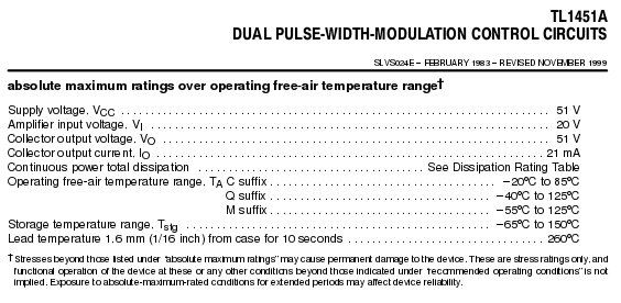

- It appears that the TL1451 error amp input has an abs max of 20V input but it's not clear if this is common mode or differential
- It's also not clear that the recommended operating range is 1.05V to 1.45V.
- The recommended operating range is suspiciously +-200mV from 1.25V which is the internal reference voltage inside the TL1451A (see the block diagram). This makes me wonder if there are protection diodes or some sort of circuitry that will conduct/damage from overvoltage events much higher than the recommended operating range but lower than the 20V abs max.
Maximum Power Point Tracker & TL1451A
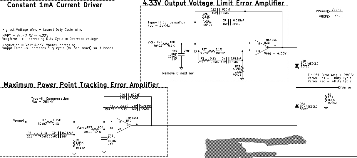
Here is the design of the MPPT which utilizes the LM6144A as an external error amplifier. Now, the idea (and this works) is to tradeoff MPPT and output voltage regulation. The MPPT error amplifier obtains a reference voltage based on temperature that predicts the maximum power point voltage since the solar panel parameters are well understood. So:
- When output power delivered to load is lower than input power from panel the MPPT does not perform power point tracking and the voltage regulation error amplifier has control.
- When output power = input power (neglecting losses) the MPPT error amplifier obtains control (highest error voltage = lowest duty cycle).
The diodes (D8A and D8B) combine the signals and let the tradeoff happen. Verror is pumped directly into the TL1451A error amplifier setup as a unity gain buffer.

Possible Design Error
OK here is where I would absolutely LOVE some clarification. It appears that during startup I see the LM6144A MPPT error amplifier rail high. The LM6144A and the TL1451A are powered from the solar panel voltage so the op-amp voltage can never be higher than the TL1451A VCC which I thought was OK when designing this. However the LM6144A turns on around 1.8V and the TL1451A turns on around 2.7V which at first was thought OK but this creates a race scenario.
The MPPT error amplifier detects the panel voltage is too high compared to the reference temperature based voltage (the measured temp signal will match the VCC voltage until it is high enough to properly operate). This causes the error amp to rail momentarily and it appears this dumps >10mA into the TL1451A non-inverting error amplifier pin 3 for several ms.
Below shows the D8A diode replaced with a 2.65K ohm resistor and D8B left unpopulated. This ensures that any current flow would be into the TL1451A from U3C above.
- CH1 = Solar panel voltage (VCC)
- CH2 = Pin 3 of TL1451 (Non-inverting error amp input of TL1451)
- CH3 = Pin 8 of LM6144 (MPPT error amp output)
It's obvious there's a near 1.25V difference across the 2.65K resistor showing 471uA of current. Regulation is maintained around 1.8V after the initial spike.

Below is an attempt to show the op-amp inputs on the TL1451 and how they are getting pulled away from each other
- Channel 2 below is Pins 4&5 of the TL1451A connected together (Feedback and inverting input)
- Channel 3 below is Pin 3 of the TL1451 with 2K resistance
- Math = CH2 - CH3
It's clear the TL1451A op-amp inputs are being pulled away from each other by 2V...

My fear is that this is stressing/breaking the TL1451A devices. I have replaced the broken ones and all seems fine but if this is what the issue is then I wonder if I have failures waiting to happen and i happened to find the ones that could resist this. Basically without current limiting resistors I'm hypothesising that I'm dumping several mA into pin 3 of the TL1451A using just diodes for feedback.
You can also see that the TL1451 error amp inputs are being pulled away from each other
Potential fix
Placement of 2.65K resistors in place of D8A and D8B seem to provide nominal operation and will limit the current to no more than 1.2mA during startup in a 6V system. below is a scope capture showing the MPPT error amp railing then the voltage regulation error amplifier taking over with two 2.65K resistors instead of diodes.
Big Questions I Would Love Answered/Help With
- Could the stresses shown above with diodes D8A and D8B cause the TL1451A to intermittently fail from startup (unrecoverable) while some survive OK hundreds of startup cycles?
- Would 2.49K resistors instead of diodes limiting current to about 1mA be sufficient to help ensure the TL1451A is NOT damaged?
Thank you
Bryce


