This thread has been locked.

If you have a related question, please click the "Ask a related question" button in the top right corner. The newly created question will be automatically linked to this question.

Transfer function of TL431 and opto coupler feedback

Other Parts Discussed in Thread: TL431, UCC2802, UCC28600

Hi,

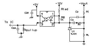
I am taking feedback using TL431 and opto coupler with type 2 compensation as shown below.

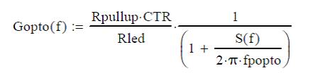
I am using the following transfer functions:

1. TL431 transfer function:

Opto coupler Transfer function:

I have few more doubts in the transfer functions;

  1. How to include the Cpp capacitor (capacitor from opto coupler emitter to ground) in the transfer function.
  2. How to calculate the opto coupler double pole frequency.
  3. Opto coupler CTR will varying from 0.8 to 1.6. Which value need to take while calculating the feedback components.

Regards,

Ashok

  • Hello Ashok,

    Does this application note help?
    www.ti.com/.../slua671.pdf

    Best,
    Michael
  • Hi, Michael

    I am considering to use UCC2802 to design a flyback.

    1) Can I use the same transfer function in the slua671.pdf (for UCC28600) for my UCC2802?

    2) The CTR (Current Transmission Rate) of opto coupler has a big range with temperature. So, CTR value will change dramatically when the operation temperature change. Since compensation calculation is based on the CTR, does that mean that the circuit could go into unstable status if temperature changes

    Thanks and Regards

    Naiwu

  • Make the post up!

    Not sure if Michael is still available to answer it, but want to know anybody else have relative experiences.

    Many thanks
  • Hello

    The article by Ridley at http://switchingpowermagazine.com/downloads/15%20Designing%20with%20the%20TL431.pdf

    should be helpful.

    please let me know if you need any further clarification

    Regards
    Colin

  • Hello Naiwu

    In answer to your second question '2) The CTR (Current Transmission Rate) of opto coupler has a big range with temperature. So, CTR value will change dramatically when the operation temperature change. Since compensation calculation is based on the CTR, does that mean that the circuit could go into unstable status if temperature changes'

    The answer is possibly - and CTR variation is one of the biggest problems in using Opto-coupler feedback. Of course it's a solvable problem because 'everyone' uses opto-coupler feedback.

    There are many causes of CTR variation
    part to part variation - 100% to 200% CTR variation is not uncommon
    CTR is a function of the LED current, If. Normally the CTR is specified at If = 5mA or so but it will reduce as If reduces, and of course If will vary as the load on the PSU varies.
    CTR is a function of temperature - as you mention.
    CTR also degrades with time - this isn't well published but over a period of years CTR can drop significantly. The rate of degradation depends on If and temperature.

    So - my advice would be to calculate minimum and maximum CTR values for your design taking into account the factors I've listed and to design your loop to be stable under all conditions.

    Regards
    Colin
  • Hi, Colin

    Many thanks for your answers about the CTR and very useful article "Designing with the TL431".

    Regards

    Naiwu