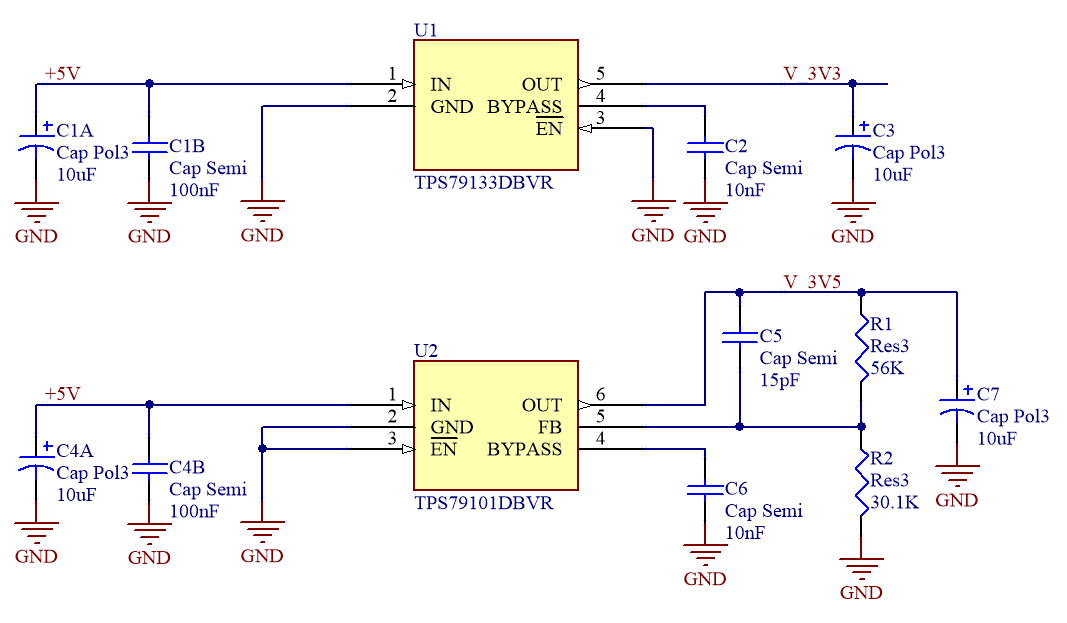
Hello, I am encountering an issue with TPS79101DBV in a prototype.
Referring to the attached image, the measured voltage at node V_3V5 is not 3.5 V but something around 3.33 V. Both regulators have +5 V for input that comes from a USB connection (after some kind of low-pass filter). Output voltage of TPS79133 (voltage of node V_3V3) is +3.298 V that is OK.
I followed the datasheet (pages 12-13) about programming the output voltage and selected R1=56 kΩ, R2=30.1 kΩ - all resistors are 0.1 W, 1%, 0603 SMT. Had I selected 3.33 V as output voltage, R1 would be 51.75 kΩ that is way outside the tolerance limits of R1.
C5 is selected to be 15 pF according to the datasheet.
C1A, C4A are tantalum capacitors; C1B, C4B are 0603 X7R ceramic capacitors. C2 and C6 are 0603 X7R too; they could be 100 nF, too, according to the datasheet but this has to do with output voltage noise and not accuracy - or am I missing anything?
Has anyone of you any idea to work around this issue?
I am thinking of removing one of R1, R2 and measure it to be 100% sure about their value.


