This thread has been locked.

If you have a related question, please click the "Ask a related question" button in the top right corner. The newly created question will be automatically linked to this question.

TPS2505 Getting very hot and frying..

Other Parts Discussed in Thread: TPS2505

Hi everyone, I have a question that has stumped me thus far and I am hoping the forums can help.
Forgive me if this is the improper forum beforehand..

I have designed a fairly simple device using and UC3A3 MCU  that is running in USB Host mode and must  provide 5v to a USB memory stick. It is powered by two AAA cells now, but will likely be using a single Li-Ion Cell with charge management in the future.

I choose the tps2505 for this task because it provides me a the dual boost 3.3V and 5V from Vin < 3V.

I am using basically an identical circuit to the application example in the 2505 datasheet, using two aaa cells and boosting up to 5V for the USBVBUS on the UC3 (USB1 on the 2505) to power the USB Stick, as well as providing 3.3V to power the UC3  circuit (LDOOUT on the 2505).

With some USB sticks, the device works fine, everything is in order, but when I use other USB sticks (generally older ones), the tps2505 becomes too hot to touch and burns out. They are likely drawing more current and the system can't keep up.

I like the simplicity of this circuit so I am trying to figure out what might be the cause of this.
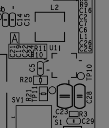
 

C28 is 10V Ceramic
C27 is 10V ELECT POLY
C5 is 16V X5R 20%
C23 is CER 10V X5R 20%

L1 is 2.2uH C3225X5R1A226M


I am using ~95k resistors on the current limiting portion of the 2505 thinking that ~200mA is enough for one USB stick. I have also set it up with ~35K resistors (~800mA max) and the 2505 burns out in that case as well.

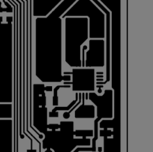
I have attached my schematic showing how it is setup, as well as noting the battery supply and 3.3/5V outputs.

If anyone has ANY ideas, please share them...I have been working on it for a while, but can't figure out what the issue might be. My next step will be to test for ringing (don't have a scope handy right now), and build a snubber circuit. My board layout is fairly tight, but there may still be some parasitic effects causing this.


What I would like to know is if there is a major flaw in my design, or if I can quickly fix this my modifying the circuit in a simple manner.


I am also open to a completely new design to provide these two sources, but i like the 2505 for its simplicity.


So far I have only been able to get samples though.. does anyone know where I can get the 2505 in more than 5 at a time sample quantities?


Regards & thanks for Reading.

OAC

  • OAC,

    Thanks for your interest in the TPS2505. In order to better understand and find a root cause for the problem you are experiencing  I would like to know the following information:

    1) What is the correct part number for the inductor? The schematic seems to indicate a 22uH instead of 2.2uH inductor and the part number given (C3225X5R1A226M) is for a 22uF capacitor.

    2) What are the connections to the ENUSB2, NRESET, USB2 and FAULT2 pins?

    3) Is it possible to get snapshot of  PCB layout, specially the ground layers?

    With thanks and regards,

    Norelis Medina


  • Thanks for the reply Norelis,

    Apologies for the typo, the inductor is in fact ELL-6PG2R2N,  which is 2.2uH. I realize the schematic says 22, but that is a typo that was fixed pre prototype..

    ENUSB2, NRESET, USB2, AND FAULT1, and  FAULT2 pins are floating as they are not used. I thought that would be fine, although I was not 100% sure about the NRESET  pin. I can easily change these if required.

    Below are sections of the layout dealing with the 2505 and a final capture of the board (rotated 90) for rough component layout. I am only able to show partial screen caps of the applicable areas at this time..

    This is merely a prototype that was rushed....but I am able to make any changes as per suggestions if there is something that could be causing this issue. I greatly appreciate ANY feedback good or bad.. It would be easier to modify component values than change the board, but if there is a critical flaw in the board design, that can be fixed.


    Thanks

    OAC

    p.s

    any word on availability of this chip in any quantity other than sample if I get this working?


  • OAC,

    Please make sure all enable signals are connected. If the USB2 switch is not used, please tie the ENUSB2 pin to ground, USB2 and FAULT2 may be left disconnected. Since you are using USB1 switch, please connect FAULT1 to a pull-up resistor as indicated in the datasheet.

    It is also a good idea to connect the TPS2505 nRESET output signal to the uC Reset input. This could help make the system more stable.

    Regarding samples, how may would be needed?


    Best regards,

    Norelis


  • Thanks Norelis,

    I am going to try those changes. I had misread the Fault1 connection as not required but it makes sense now that I re-read it.

    Do you suggest looking into a snubber circuit as well?

    I will tie a 1K 1/2w resistor to VAUX and that should be ok right? (10mA max).
    I will tie ENUSB2 to gnd, and also link up the reset pins.

    Also, I am thinking that 30 or 40 samples would be allow me to move forward with this product until they are shipping from digikey etc.

    OAC


  • OAC,

    1KOhm should be OK. Typicaly use 10KOhm in the EVM.

    To request larger sample quantities please contact your local TI Sales Representative.


    Best regards,

    Norelis

  • OAC,

    The heating of the IC may be due to the USB switch current limit being activated when there is a short on the load. When this occurs, significant power may be dissipated through the switch. The FAULT output signal will go low when the current limit is activated. This may help you on your debug, The IC will automatically shut down once the thermal shutdown threshold temperature has been reached to protect the IC.

    We replicated your setup, and can only get the device to heat up when the output of the USB switch is shorted to ground (as expected). The IC however does not get damaged and remains fully functional.

    Once thing you may look at is your PCB gound layout. Please make sure you have a solid ground connection to the thermal pad. A good practice is to have a dedicated ground layer.

    I hope this helps.


    Norelis


  • Thank you Norelis..

    I will run some testing and see if I can debug this. Thank you for all of your help. I am curious why some USB sticks work and others heat the unit up though. I will get to the bottom of it.

    Regards

    OAC

  • Older USB sticks may draw significantly more current than the newer ones. The 95K resistor in ILIM pins will limit the switch current to ~300mA. A USB 2.0 compliant stick may draw up to 500mA causing the current limit in the TPS2505 to kick in. Try changing the value of the resistor in the ILIM pin to 35K-40KOhms this will prevent current limiting and hence heating in for USB compliant load.