This thread has been locked.

If you have a related question, please click the "Ask a related question" button in the top right corner. The newly created question will be automatically linked to this question.

LM5116: About Current limit

Part Number: LM5116

Hi.

I used the LM5116,designed it,and created a prototype.

The design parameters are as follows.

Vin: DC18-30V

Vout:DC16V/13Amax

Chf:33pF,Rcomp:56k,Ccomp:270pF( form LM5116_quickstart.xls)

Rcramp:240k,Cramp:820p

Rs 2mohm,Fsw:100kHz

Q1.Increase the load(0->13A),Switching operation stops at about 7A.Why?

     Current limit::55A? I hope I can output 13 A or more.

Q2.Is there a way to disable the current limit function?

Q3.Reducing the value of Rcramp made it possible to flow a large current.Why??

I am very embarrassed. I am waiting for an answer.

Best regards.


  • Hello user357205584,

    I have directed your question to the appropriate team. You should receive an answer soon.

    Regards,
    Ulrich
  • Hello,

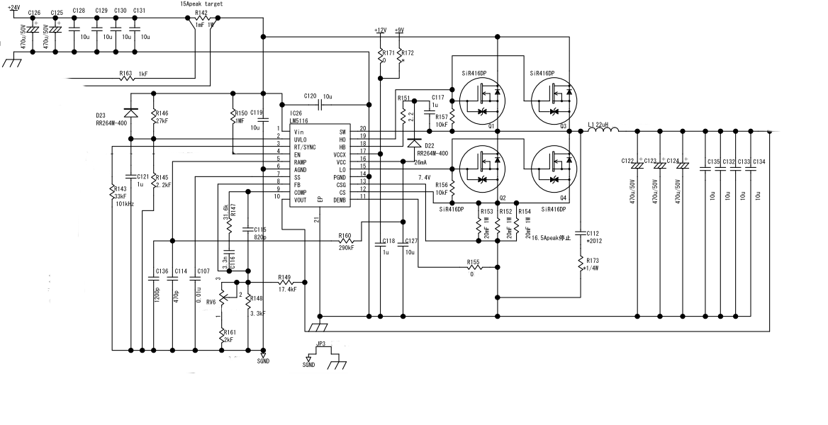
    There is a possibility that noise on the current sense signal is causing the issue?  have you followed the guidlines for connecting the CSG pin?  do you have a schemtic you can share?

    Thanks.

  • Hi David,

    I think that there is a possibility that noise is causing the issue.

    I tried to reduce the value of Rs, but the symptoms did not change.

    After the switching operation became unstable, the LM 5116 was damaged.At that time, it was 3 V output with no load.

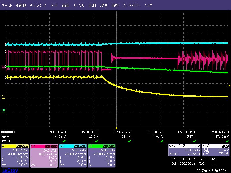
    I attach the schematic,and the waveform when the switching operation is stopped is also attached.(Ch1:Iin 2A/10mV,Ch2:LosideFET Drain,Ch3:Vin,Ch4:Vout)

    I do not know guidelines on CSG. please tell me.Can you also answer,Q2 &Q3?


    Q2.Is there a way to disable the current limit function?

    Q3.Reducing the value of Rcramp made it possible to flow a large current.Why??

  • Hello,
    In response to your two questions please see below.

    1. You cannot disable the current limit input as this is a current mode control IC and the current information is used to generate a Ramp for the PWM comparator, i.e. it is very much part of the control loop and disabling it will make matters worse especially at high load currents.
    2. The Rramp and Cramp are used to add slope ontop of the Current sense signal to avoid Sub harmonic oscillation. The more or less slope that is added will have a direct effect on the stability of the current loop and the load current capability of the convertor.

    Back to your issue:
    You need to make Sure you are kelvin sensing the voltage across the Rsense Resistor. This means you should not tie the GSG pin to Gnd at the IC, rather the Ground connection of GSG must be tied to the Ground side of the Rsense resistor only. This is where the GSG pin get tied to Gnd.

    Also I suggest placing 2 100ohm Resistor in series with CS and GSG and placing a 100pF capacitor from CS to CSG at the IC to see if things improve? The RC will serve as a filter to the current sense input.