This thread has been locked.

If you have a related question, please click the "Ask a related question" button in the top right corner. The newly created question will be automatically linked to this question.

LM22675: Measuring 1.8V instead of 5V on the output

Part Number: LM22675

Support Path: /Product/Development and troubleshooting/Help with board layout or design considerations/Find recommended layout for a TI device/

Hi all,

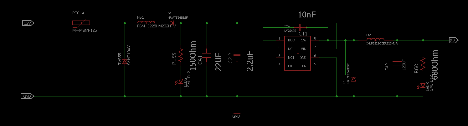
I created a prototyping PCB, as voltage regulator I use the lm22675QMR-5.0/NOPB.

I when I measured the output voltage of the voltage regulator I expected to measure 5V instead of the 1.8V

Now I found out that I accidentally connected the Feedback line before the inductor, instead of behind it.

My question is, could this be the problem that I measure 1.8V instead of 5V? If not is there another mistake in my schematic?

Kind regards,

Toon Mertens


  • Hello,

    Besides the issue you identified (with FB pin) your schematic looks OK. In general we suggest pulling EN pin to VIN thorough large resistor (for example 470k), see device datasheet for details.

    As far as measured output voltage is concerned it is most likely related to the point where FB pin was connected. We suggest you modify the connection and re-measure output voltage.

    Best regards

    Brani