This thread has been locked.

If you have a related question, please click the "Ask a related question" button in the top right corner. The newly created question will be automatically linked to this question.

CSD17575Q3: about Junction temperation calculation at Ta = 100⁰C

Part Number: CSD17575Q3

Hi team

for CSD17575Q3,

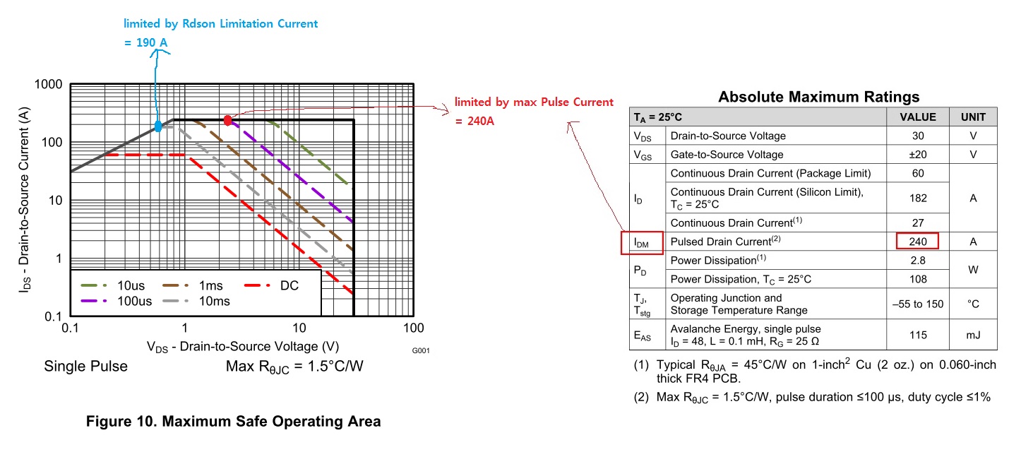
Continuous Drain Current is defined 27 A at RӨJA = 45 ⁰C/W and Ta = 25 ⁰C.

I want to estimate the allowable Continuous Drain Current at Ta = 100 ⁰C with RӨJA = 45 ⁰C/W and Vgs = 10V/Id = 25A conditions.

Max Rdson at Ta = 100⁰C would be 3.91 mohm(= 2.3 mohm x 1.7).

the allowable Continuous Drain Current at Ta = 100 ⁰C would be 16.73 A [= root(( Tjmax - Ta )/(RӨJA x Rdson)) = root(( 150 ⁰C - 100 ⁰C)/(45 x 3.91 mohm))]

my calculation above is correct ?

  • Paul, 

    Your calculation is correct. Just keep in mind that in application, the actual RthJA of the board is highly dependent on your thermal environment. But if we were to spec a current rating for Ta = 100deg base on RthJA = 45degC/W, we would arrive at the same current you calculated. 

  • Hi Brett

    I already watched the video " Understaning MOSFET datasheets: Current Ratings",

    and I have further questions as below to exactly catch what is your point in mentioning Idw calculation example.

    I made several examples for easy communications as below.

    [1] our SQA curve is acheived at Tc = 25 degree ?

        if it is done at Tc = 25⁰C in D/S, the safe Id current would be more shrunk by Tc increasing more up.

    [2] with 100 usec pulse duration and 1% duty ccyle for CSD17575Q3, I calculated Max Idm = 486 A.

         SOA curve at 100 usec line meets at Max Idm Limited = 240A which is limited by Abs max Idm.

         my calculated Idm = 486A is far above SOA's Max Idm Limited = 240A.

         hence, the Max Allowable Idm should be below 240A at the given conditions, right ?

    [3]  with 10 msec pulse duration and 50% duty cycle for CSD17575Q3, I calculated Max Idm = 153 A.

          SOA curve at 10 msec line meets at Rdson Limited = 190A which is limited by Rdson limitation.

          my calculated Idm = 153A is below SOA's Rdson Limited = 190A.

         hence, I can use my calculated Max Allowable Idm = 153A at the given conditions, right ?

    [4] for the application using 10 msec pulse duration and any certain duty cycle for CSD17575Q3,

         the max allowable Idm on borad level should be 190A by "Rdson Limited" or 240A by "Abx max Idm limitation" ?   

    [4] assuming that the board consumes the actual Idw = 60A at Vgs = 20V with 100 usec pulse duration and 1% duty cycle for CSD17575Q,

         but the 100 usec line is limited by 7A at Vgs = 20V on SOA.

         is it OK of the board to consume actual Idw = 60A at Vgs = 20V still ?    

         SOA purpose is not like that, right ?

         I think SOA uses the regulated Vds and Id at test, and SOA can be refered to compare several FETs's performance relatively,

         so I think everything would be Ok if the transient Vds = 20V will disapper in very short period compared to 100usec.


  • Paul, 

    Let me address your questions one at a time. 

    1) Yes datasheet SOA testing is done at Tc = 25. If the case temperature starts higher, the max Id would be lower. 


    2) You are correct. 240A was the maximum pulsed current rating our packaging engineers felt comfortable assigning to a Q3 package so all current calculations above this value are capped to 240A on the SOA. 


    3) Correct, but you still need to be careful your real ZthJA in your board does not overheat the part during this pulse. If you are using the ZthJC curve for calculations, just be aware that the actual thermal impedance of your board can vary. 

    4) 190A does not come from Rdson limitation line but rather pulsed Idm limit (hence why the curve is flat). It is 190A by pulse current limitation for that pulse duration, 10ms. It's best not to think of the Rdson line as a real limitation. Whenever, you are on the line, you can always apply more Vds to get more current, but eventually, you will hit another limitation (be it a pulsed current limitation which would be a flat line like the 190 A, or a max power limitation which would be a downward sloping line). 

    5) The SOA is primarily meant to show how much power the FET can dissipate in the saturation region, when Vgs is held lower in order to regulate the drain to source voltage. If you plan on fully turning on the FET (fully enhancing the device), then conduction losses are the most relevant thing for you to consider, and whether your thermal environment can handle those losses. If you plan to operate in the low Vgs, high Vds region in order to limit current for some time (like for a Hot Swap or ORing application), then SOA is critical. 

    If you are asking about a turn off event, then 20Vds will only be across the FET for a very short time. You would have to look at a waveform to examine exactly how long it takes the FET to turn off, and what the current is during that time. If the power loss is substantial during this interval, then the SOA may in fact be often, but generally turn off is quick enough that this is not the case.