A related question is a question created from another question. When the related question is created, it will be automatically linked to the original question.
If you have a related question, please click the "Ask a related question" button in the top right corner. The newly created question will be automatically linked to this question.
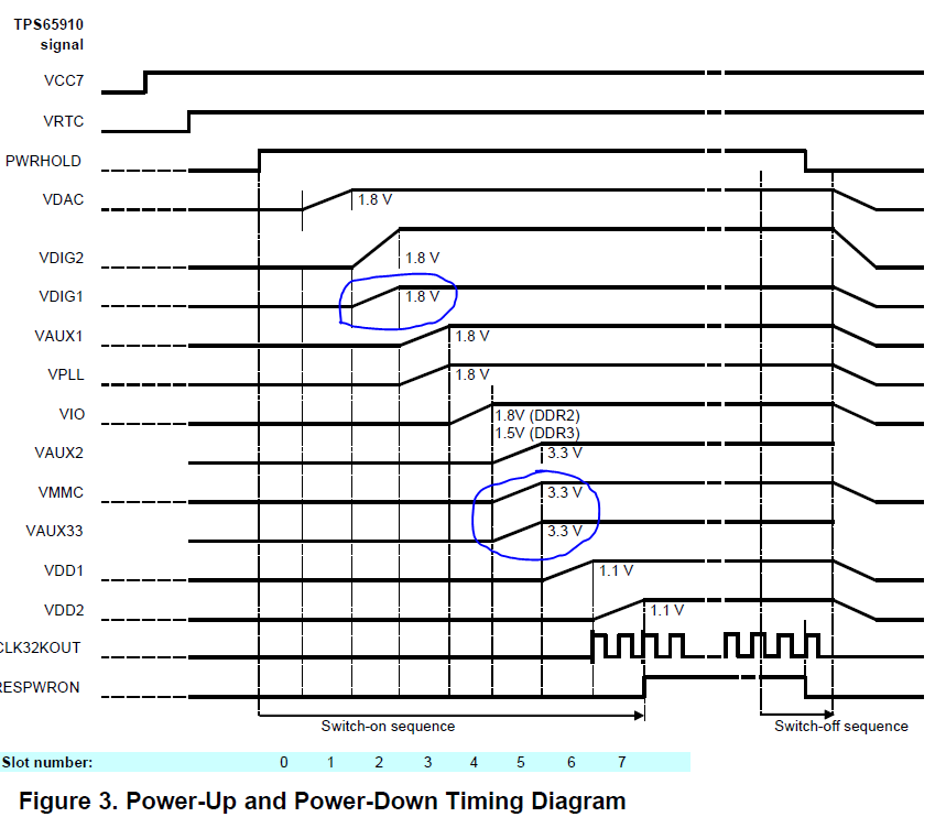
What is the time scale of your scope shot? Can you attach a scope shot at 2ms/div? I noticed that your VAUX33 and VMMC are rising at the same time as VDIG1 when they should rise after the VDIG1. Attached is the timing diagram from the User's Guide.
Natasha-san
Time scale is 20us/div.
Attache waveform was TPS659108EVM, because VDIG1, VAUX33 and VMMC were started at the same time.
My question is not start up timimg, it is start up behavier.
Only VDIG1 and VDIG2 start up steeply, all other LDO's start up monotonically. Why?
The slope of the start up waveform is related to the capacitance and current on the pin. On the TPS659108EVM, all these lines have the same capacitance. Thus, the current supplied to the pins is most likely the differentiating factor. VDIG1 and VDIG2 are supplied by VCC6, while VMMC and VAUX33 are supplied by VCC3.
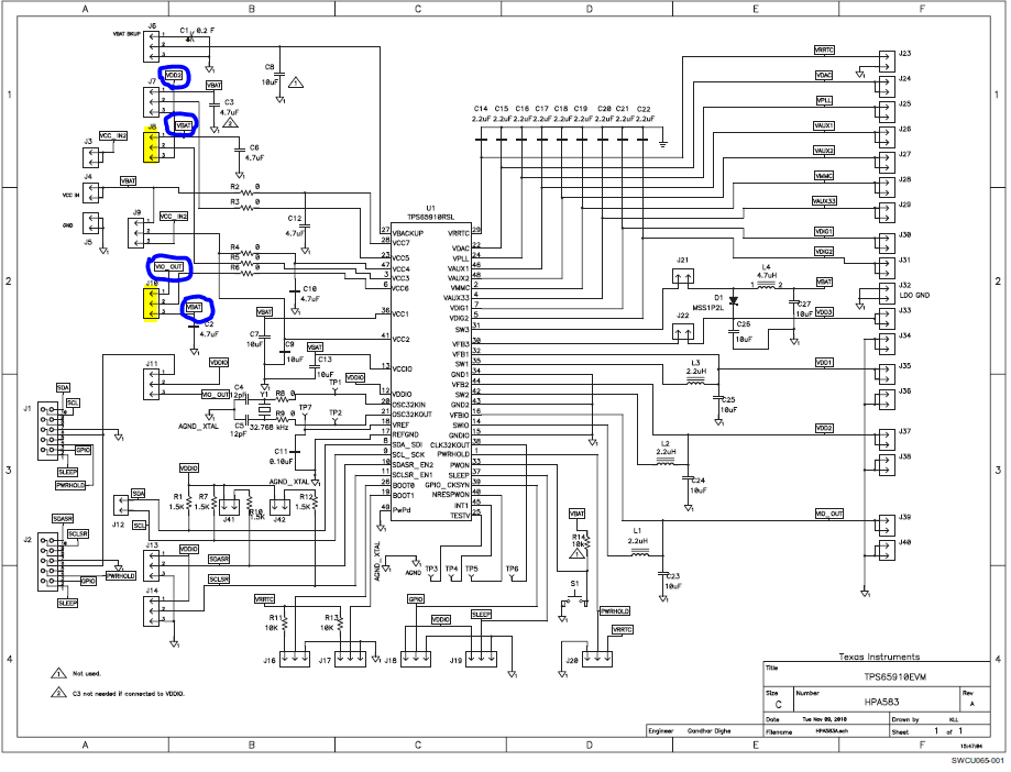
If you look at the TPS659108EVM User Guide, there is a schematic of the board that shows all these pins. On this schematic, it shows that VCC3 and VCC6 both use jumpers to determine how the pins are supplied with power. Depending on the settings of the jumpers on the board, there will be different amounts of current supplied.
Thus, you can move the jumpers on the EVM to change how the power is being sourced and change the slope of the waveforms you are seeing on power up. Below is the schematic for reference. The highlighted jumpers are the ones affecting the slopes on the waveforms you attached. The blue circles indicate the options you have to source those pins.
After working through this in the lab, it seems that this may be the result of the inherit architecture of the device. I have attached my waveforms for your reference. When zoomed in, these waveforms (VDIG1, VAUX33, VMMC in that order) have the same slope qualities as your scope shot. The only difference is the start up timing - VMMC rises before VAUX33, rather than at the same time.
Please let me know if you are experiencing any further troubles or concerns.