This thread has been locked.

If you have a related question, please click the "Ask a related question" button in the top right corner. The newly created question will be automatically linked to this question.

TPS61088: IC is damaged when loaded with PTN78000A

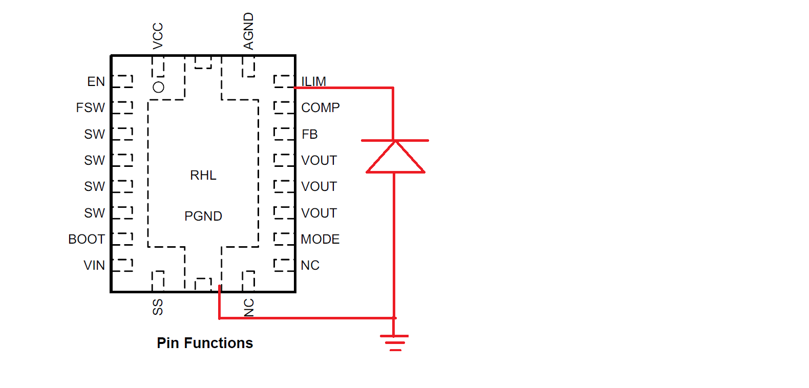
Part Number: TPS61088
Other Parts Discussed in Thread: PTN78000A,

Hi,

We built a custom circuit containing the TPS61088 IC and the PTN78000A module. My test setup is as follows:

3.7V from Bench power supply is input to TPS61088 which is used to boost it to +12V. Then this +12V is input to PTN78000A which is used to generate -12V.

Test results:

1. Testing the TPS61088 alone using a +3.7V input from the bench power supply with no load was successful. Then we started adding resistive loads of 300, 250, 200 and 150 Ohms individually and it outputs the required current and voltage drawing 306mA at 150 ohms from the +3.7V with no issues.

2. Testing the PTN78000A alone using a +12V input from the bench power supply with no load was successful drawing 39mA.

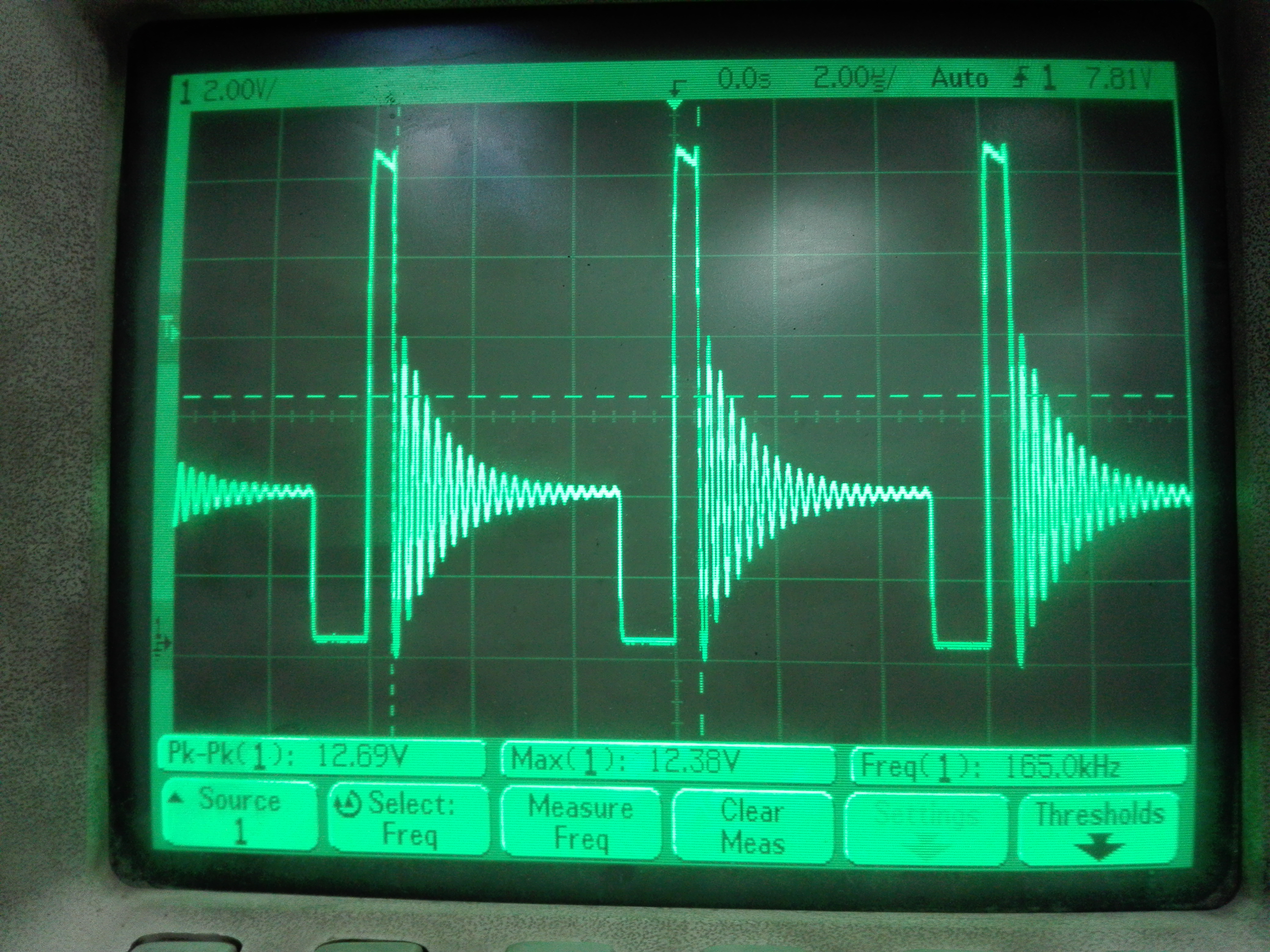
3. Testing both TPS61088 and PTN78000A connected in series (TPS is loaded by PTN) as described in the test setup above was unsuccessful. The bench power supply has a current limit set to 1A, when we power it on it immediately disconnects indicating that there is something wrong in the circuit. We found that the "SW" pins of the TPS61088 are all shorted to GND! We made this test 4 times suspecting the inductor and other passives and unfortunately lost 4 ICs in the process and still can't figure out what the issue is.

** ADDED 16/4/2017

We are suspecting the 220uF at the input of the PTN78000A is causing a high in-rush current that burn the TPS61088. To test this assumption we did the following:

- Connected a new TPS61088 IC.

- Removed the PTN module from circuit

- Tested TPS without the 220 µF capacitor. The TPS booster worked fine (it is loaded with 47 µF capacitor of its own).

- Added resistor (22 Ohms) in series with the 220 µF capacitor to limit in-rush currents. The TPS booster burned out again (short at inductor input pins again).

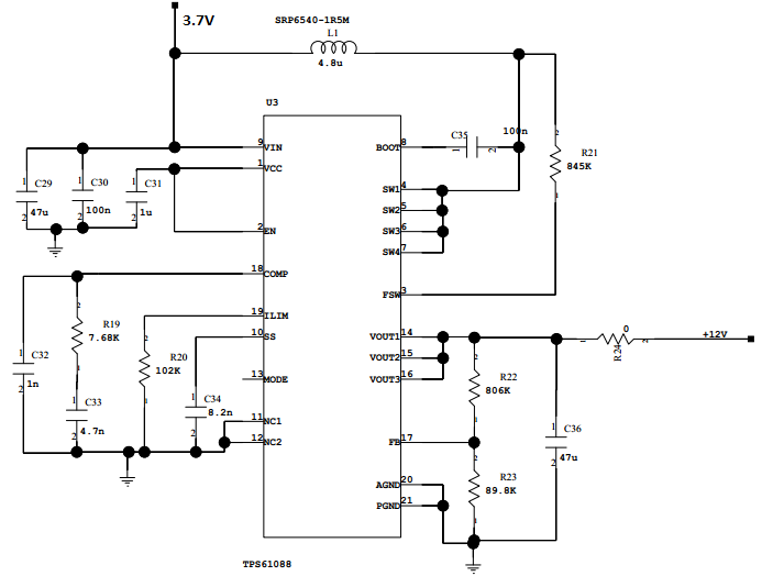
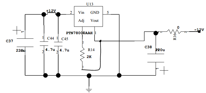
Below is the schematic of the TPS61088 and PTN78000A:

Regards.

  • Hi Sir,

    I guess there may have some soldering issue which cause the shortage.

    Did you test the TPS61088 circuit alone? Be sure the output is  OK before  connect it to the load.

  • TPS61088 circuit is working good according to the required design specs using TI software tools (WEBENCH Designer).

    It draws alone 1mA from power supply and its output is 12V.

    No short circuit found.

  • Thanks Helen for following our issue. As mentioned in point #1 in the test results, we tested it alone and worked with no issue. This short circuit between SW and GND appears only when loaded by the PTN78000A module and not any other resistive load.
  • Please measure the impedane from the Ilim pin to GND, it should be 102k according to your schematic. I'm wondering whether it is shorted to GND.

  • Thank you Helen,

    We are suspecting the 220uF at the input of the PTN78000A is causing a high in-rush current that burn the TPS61088. To test this assumption we did the following:

    - Connected a new TPS61088 IC.

    - Removed the PTN module from circuit

    - Tested TPS without the 220 µF capacitor. The TPS booster worked fine (it is loaded with 47 µF capacitor of its own).

    - Added resistor (22 Ohms) in series with the 220 µF capacitor to limit in-rush currents. The TPS booster burned out again (short at inductor input pins again).

    What do you suggest?

  • Thanks for the update.

    Did you test the inductor current? If the burn always happended at the startup when there's a 220uF cap at the output side, then you should test the soldering of the Ilim pin. if the Ilim pin is well soldered, the inductor current will be limited by the Ilim value. If this pin is not well soldered, the current will be very big during startup.

    There's a diode in parallel with GND and Ilim pin, if you can test out that diode, then it is well connected. if you can't test out the diode, then the IC should be resoldered. Please refer to the following picture! Could you please share the detailed application information for us? Like in what kind of equipment? Volume? My email address is helen-chen@ti.com

  • The soldering of the Ilim pin is test and soldered well. the value of Rlim used is 102K ohm.

    The used inductor is SRP6540-1R5MCT-ND.Inductance

    Inductance 1.5µH
    Tolerance ±20%
    Current Rating 11A
    Current - Saturation 11A
    Shielding Shielded
    DC Resistance (DCR) 10 mOhm Max
  • The bench power supply has a current limit set to 1A. As there are big EL cap at the input and output of the PTN78000A, try to remove the the input 220uF, change the output 220uF cap to to a smaller one to check whether it could be help. Becuse it is easier to trigger the power supply 's current limit protection with big cap load.


    Or coulld you change make the power supply's current limit level higher, like 3A-5A.?


    And once more, could you please show the waveform of the inductor to me? because if the power supply current is limited, it is hard to destroy the TPS61088.

  • The minimum requirements for the input bus of PTN78000A is 100μF of nonceramic capacitance(CAPACITOR RECOMMENDATIONS FOR THE PTN78000).

    This input cap is removed and tested the module alone and its input from power supply, it works fine.

    the power supply current limit was 1.5A during test.

    The last time i have tested it, i removed PTN78000A and connected a 22ohm in series with the input cap 220uF, but the power supply switch is disconnected and found short circuit on SW pin of TPS61088 with GND.

    Unfortunately, I don't have spare of TPS61088.

    The following waveform of SW pin ( inductor to SW pin of TPS61088)

  • I want to check the layout, could you please send the pcb layout to me? helen-chen@ti.com

  • Thank you, Helen, I sent the layout to the mentioned email. Please notice that we didn't split PGND and AGND. I am not sure if this can lead to a damage to the IC!

  • I check the pcb layout, found the output voltage trace is long and thin. And didn't found the output cap C36 in the pcb. Longer trace will cause higher voltage spike at the SW pin. And I noticed Rsw=845k ohm, why choose such high resistor, which means the operation frequency is very low and the indcutor is easy to be saturated, please use Rsw=249k in your application, L=1.5uH.

  • Dear Eng. Helen

    Thank you for your informative contributions.

    We still have several questions:

    1- We still can not pin point the root cause of the failure our five  TPS61088 ICs. In four of these failures, this module was loaded with  PTN78000A module, with 47µF ceramic and  220 µF electrolytic capacitor shunted in between the two modules. In the fifth case, we had no load to TPS61088 IC other than the 47µF ceramic and  the 220 µF electrolytic capacitor. In this case 22 Ohm resistor was added in series with the electrolytic capacitor to limit in rush currents.

    What is the most likely reason for this IC failure (large C load ?, layout errors ?, low switching frequency ?, poor solder ? ....?)

    2- What we need is +/- 12 regulators to feed small (<50 mA currents) with shutdown capability. All our stock of TPS61088 IC is burnt now. Do you recommend to search for another TI (more robust)regulator(s) or continue our trials with TPS61088.

  • The main reason of failure is low frequency and poor layout if the soldering is OK.. This IC support big C load applcation if it is well soldered. But as I didn't have your board on hand, so you need to check the solder by yourself. Like the Ilim pin, there's a diode in parallel with the Comp, FB, Vout, SS ... and the PGND.

    So please change the Rsw to 249k first based on your 1.5uH inductor, then put the 47uF ceramic cap very near to the Vout and PGND. As what is the TPS61088 datasheet recommended.