This thread has been locked.

If you have a related question, please click the "Ask a related question" button in the top right corner. The newly created question will be automatically linked to this question.

CSD18502Q5B: Supply 24V to an sensor cooling system driven by 3.3V of Microcontroller..

Part Number: CSD18502Q5B

Hi,

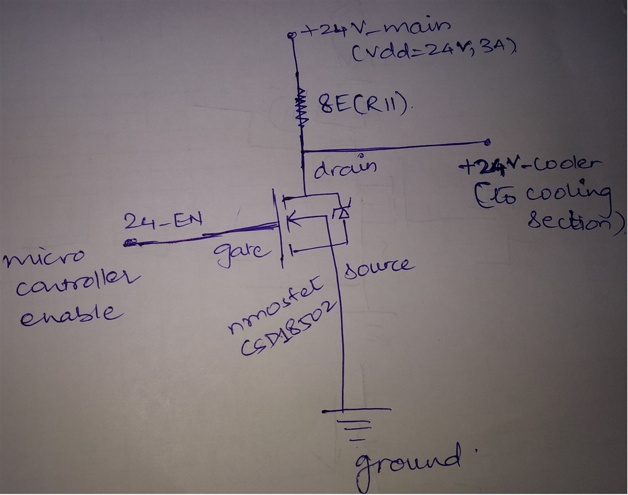
I have implement CSD18502Q5B power MOSFET which is driven by gate voltage via GPIO of MSP430. I need to supply 24V, 6A   to a cooling assembly of an IR sensor.

I have attached the schematic with the post.

Please let me know if this circuit is correct..

4186.POWER SECTION.pdf

Regards,

Dhara

  • Dhara,
    I am not sure I understand your question. If you just want the FET to act as a pass FET, it should have no problem delivering 6A, and a 40V breakdown is plenty under the 24Vin so long as you don't have much ringing on the FET.
  • Hi Brett,

    When I power on my board and drive gate with (Vgs=)10V input, the resistor R11- 10E (8E mentioned in schematic) on the drain with Vdd starts heating up.

    What can be the reason for this if this schematic seems fine..?
  • What is the resistor value? Really I can only speak to the MOSFET but I can run this by our apps team.
  • Hi Brett,

    Resistor is 10E leaded with 2W capacity. If you can please look into this, would speed up my development.
    I hope the purpose of this schematic is clear..

    I need to supply 24V-3A, to the cooling section, controlled by MSP430. So I have used power MOSFET CSD18502Q5B with gate driven by the GPIO of controller. The drain is connected to VDD (=24V, 6A) with a series resistor of 10ohm (leaded, 2W).

    When I power on the card and give high (3.3V) on gate, the resistor on drain (10ohm) starts heating up.

    Any suggestions or modifications in the design to implement this switching of 24V,3A to cooling section will be helpful.


    Thanks,
    Dhara.
  • Darah, 

    One thing that is not clear from the schematic is how is the fan being connected to ground? Could you provide a rough schematic of how the FET, the limit resistor, and the fan are all connected? 

    Another issue you may be running into is the CSD18502Q5B is only rated down to 4.5Vgs. Anything below that is going to be very high on the Rdson vs. Vgs curve, and we make no guarantee about the resistance of the part in this range. 

    Can you also specify what frequency and duty cycle you anticipate operating at? 

  • Hi Brett,

    Where is the Fan connected to ground in schematic..?

    In the schematic J5 is the connector where the enable signals are routed to microcontroller. For CSD18502Q5B, gate enable signal is 24V_EN (J5.1) routed to microcontroller. The Vdd to MOSFET is 24V, 3A (+24V_Mains) and the output from drain to cooling section is 24V, 3A (+24_Cooler) routed via D-Sub 9 Pin connector (J4.5, J4.9).

    I noted the Vgs value in the data-sheet of CSD18502Q5, so now I need to apply Vgs >/= 4.5V to enable switching action.

    No specific/ continue switching action is required. The output of the MOSFET, (+24_Cooler) supplied to cooler, will draw 3A initially and after its temperature reached a specific value, its current will be reduced to 150-200mA. Later on till the entire

    process/ testing of sensor this supply will be kept ON.

    Thanks,

    Dhara.

  • Thank you Dhara,
    I have forwarded to our apps engineers. I will let you know if they have any more questions.

    Let me know if you see a change when driving at 4.5Vgs.
  • Hi Brett,

    Thanks for the help.

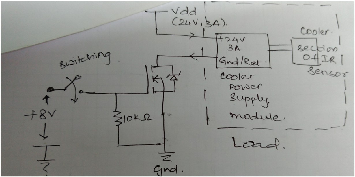
    This is the actual application I want to design. I need to switch the supply (24V,3A) to the cooler power section.

    Here in this case the supply section and cooler is the load for MOSFET which is connected in series with the drain of MOSFET and Vdd.

    The cooler power supply (load) connected in the circuit is correct..?? Is this design correct..??

    Thanks & regards,

    Dhara

  • Dhara, 

    I see that there is an 8V gate drive now so I think this should work. But I have forwarded to our apps team for comment.