This thread has been locked.

If you have a related question, please click the "Ask a related question" button in the top right corner. The newly created question will be automatically linked to this question.

EM1402EVM: Active balancing demo problem

Part Number: EM1402EVM
Other Parts Discussed in Thread: LAUNCHXL-TMS57004, BQ76PL455A

Hi,
I am having problems getting the active balancing demo to work on my EM1402EVM / LaunchXL-TMS57004 setup.

I am using the demo software tms570bms-1.0 and tms570bmsgui-1.0 downloaded from here: www.ti.com/.../tidcbz0

I modified the LaunchXL-TMS57004 board as detailed in the application note (tidubi0.pdf) by removing R8/R9 and connecting the signals to J4.1/J4.2.

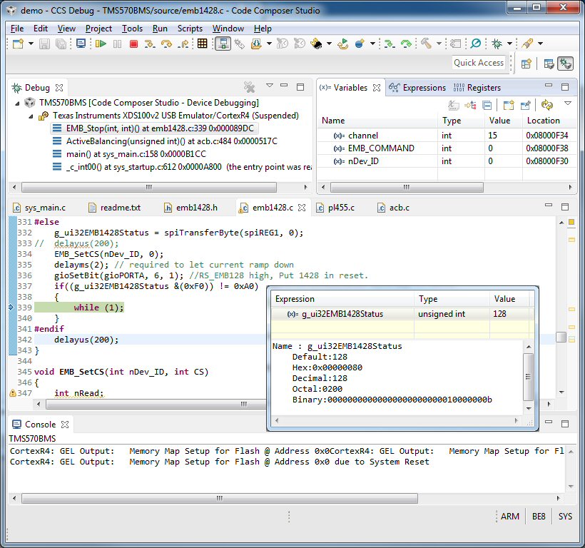
I compiled the code in Code Composer Studio and then run it in debug.  When I enable balancing via the gui app, I notice that the TMS570 code hangs in an infinite while(1) loop in file emb1428.c line 339.

As this is associated with the SPI, I tried commenting out the "#define TMS570SPI" in file emb1428.h, which appears to then make it run SPI in emulated mode. I am unsure which it should be or if it matters.

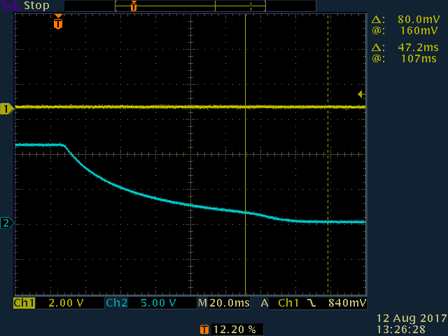
In this mode, the code does not hang and the balancing appears to be partly working in that there appears a slight dip in the voltages read from the cells for 1 second in every 4, which coincides with the LED D4 flashing on the EM1402EVM.


The problem seems to be that the lower voltage cell in not receiving any charge at those times.

My setup is 16 off 18650 Li-ion cells in series (1p16s) and 3 more in series acting as the separate 12v battery.

Does anyone have any suggestions as to where I should be looking to solve this?  I would like to have the demo working as expected before moving on to doing my own customisations.

gui1.tif

  • Hi Cliff,

    What kind of balancing current are you trying to use?

    Could you send me a screenshot of the code where it gets hung up, while you are debugging?

    As a future note, I would try to use 4s for the 12V battery. With 3S, you can't get much charge out before hitting the UV protection for this cell.

    If you replace that cell with a higher charged cell, does it work?
  • David Wiest Jr said:
    What kind of balancing current are you trying to use?

    I have not set (of found where to set) the charge current and have assumed that the demo defaults to something suitable for testing.
     

    David Wiest Jr said:
    Could you send me a screenshot of the code where it gets hung up, while you are debugging?


    David Wiest Jr said:
    As a future note, I would try to use 4s for the 12V battery. With 3S, you can't get much charge out before hitting the UV protection for this cell.

    Noted. Now using four cells.

    David Wiest Jr said:
    If you replace that cell with a higher charged cell, does it work?

    Have now swapped a few cells and all are now between 3.8 and 4v and none are showing OV or UV in the GUI.  Still not seeing any charge current.

  • I am having the same problem as Cliff. When I hit "balancing on" on the GUI it continues to just read the voltages but doesn't actually balance any of the cells. It doesn't draw any charge current. Has anybody found a solution to this?
  • All,

    For some clarification, the GUI works only with the bq76pl455A, not the EMB chipset. My understanding, if you are following the TIDM, is that the GUI communicates to the TMS570 through a virtual/emulated comm port, and then the TMS570 sends the SPI commands (or uses the pl455 GPIO's to bit-bang SPI).

    Has anyone put a logic analyser on the SPI lines, or the UART? This should help us figure out where the problem is occuring.
  • I have now done some further investigation into this.  The section of code where there seems to be a problem is in the function EMB_Stop() in file EMB1428.c:

    248   void EMB_Stop(int nDev_ID, int channel)
    249   {
    250   	int nRead;
    251   	BYTE bTemp;
    252   
    253   	switch(channel)
    254   	{
    255   	case 1:
    256   		EMB_SetCS(nDev_ID, nCS_BOTSTACK);
    257   		break;
    258   	case 2:
    259   		EMB_SetCS(nDev_ID, nCS_BOTSTACK);
    260   		break;
    261   	case 3:
    262   		EMB_SetCS(nDev_ID, nCS_MIDSTACK);
    263   		break;
    264   	case 4:
    265   		EMB_SetCS(nDev_ID, nCS_MIDSTACK);
    266   		break;
    267   	case 5:
    268   		EMB_SetCS(nDev_ID, nCS_MIDSTACK);
    269   		break;
    270   	case 6:
    271   		EMB_SetCS(nDev_ID, nCS_MIDSTACK);
    272   		break;
    273   	case 7:
    274   		EMB_SetCS(nDev_ID, nCS_MIDSTACK);
    275   		break;
    276   	case 8:
    277   		EMB_SetCS(nDev_ID, nCS_MIDSTACK);
    278   		break;
    279   	case 9:
    280   		EMB_SetCS(nDev_ID, nCS_MIDSTACK);
    281   		break;
    282   	case 10:
    283   		EMB_SetCS(nDev_ID, nCS_TOPSTACK);
    284   		break;
    285   	case 11:
    286   		EMB_SetCS(nDev_ID, nCS_TOPSTACK);
    287   		break;
    288   	case 12:
    289   		EMB_SetCS(nDev_ID, nCS_TOPSTACK);
    290   		break;
    291   	case 13:
    292   		EMB_SetCS(nDev_ID, nCS_TOPSTACK);
    293   		break;
    294   	case 14:
    295   		EMB_SetCS(nDev_ID, nCS_TOPSTACK);
    296   		break;
    297   	case 15:
    298   		EMB_SetCS(nDev_ID, nCS_TOPSTACK);
    299   		break;
    300   	case 16:
    301   		EMB_SetCS(nDev_ID, nCS_TOPSTACK);
    302   		break;
    303   	}
    304   
    305   	int EMB_COMMAND = 0x00;
    306   
    307   #ifndef TMS570SPI
           // unused code removed for clarity
    331   #else
    332   	g_ui32EMB1428Status = spiTransferByte(spiREG1, 0);
    333   //	delayus(200);
    334   	EMB_SetCS(nDev_ID, 0);
    335   	delayms(2); // required to let current ramp down
    336   	gioSetBit(gioPORTA, 6, 1); //RS_EMB128 high, Put 1428 in reset.
    337   	if((g_ui32EMB1428Status &(0xF0)) != 0xA0)
    338   	{
    339   		while (1);
    340   	}
    341   #endif
    342   	delayus(200);
    343   }
    

    The following screen shots show the state of the signals from the beginning of the function, triggering on the first rise of SCLK.

    The first byte is enabling nSC_BOT and the second is reading the status from the EMB1428 at line 332.


    The value read into g_ui32EMB1428Status at line 332 is 0x80 which matches what is seen in the waveforms. 

    According to the EMB1428 data sheet bits [7:4] of this value represent Fault[3:0] respectively.

    A fault value of 1000b is listed as meaning "CS falling edge while the EMB1428 is still waiting for a transition on DONE (rising or falling edge)".

    As can be seen on the analog trace (yellow is SCLK, but too small to see, and blue is DONE), with a longer timebase, the DONE signal was indeed high and takes around 120mS to decay down to 0V.

    But it is line 336:

    gioSetBit(gioPORTA, 6, 1); //RS_EMB128 high, Put 1428 in reset

    that actually causes the DONE line to go low which is after SPI command.

    So what happens is the code doesn't see the value 0xA0, which is listed as "No Fault Condition", so the code effectively hangs by getting stuck indefinitely at while(1);

    I am confused by this and something does not seem right to me.  I am new to this range of TI chips and am struggling to fathom exactly what is wrong and why the evaluation board and code do not work “out of the box”.

  • Nobody knows?  :-(

    I did notice that this web page:

    http://www.ti.com/tool/TIDM-TMS570BMS#0

    from which I downloaded the example code, shows a picture of an eval board that is very slightly different to the one I have, which is like the one shown on this web page:

    http://www.ti.com/tool/em1402evm

    Could there be two issues of the board requireing different software?

  • Hi Cliff,

    I apologize for the delayed response - the reply notification got buried in my inbox.

    Good debugging! Those are certainly useful waveforms.

    The EVM used in the TIDM was an older "engineering" build of the board, one of the early iterations made during the development. The EVM is the latest and greatest, so to speak. So there certainly could have been a change made that effected it. Let me try to dig up the older version of the schematic - it should be archived in our servers somewhere (it wasn't me that made the board, unfortunately. If it was, i could just pull it up!)

    One thing that you may want to try, if possible: add some delay, so that CS doesnt change states. It should only be a couple hundred ms, i would guess.

    I do know that this is something that was relatively common (running into issues with the time it takes for the converter to ramp down current to 0, and consequently change the state of the "DONE" pin")