This thread has been locked.

If you have a related question, please click the "Ask a related question" button in the top right corner. The newly created question will be automatically linked to this question.

TPS736: TPS73601 output problem

Part Number: TPS736
Other Parts Discussed in Thread: TPS730

Hello Sirs,

Would you pls help to check this problem ?
 
We use TPS73601 supply a CMOS sensor Vdd 2.8V . Normal case the CMOS sensor 2.8Vdd will befully supply by LDO tps73601.
But there's a special condition when system off(LDO tps73601 also shutdown) and CMOS sensor receive high brightness light ex: sunlight. There's a -500mV appeared at CMOS Vdd pin . It will cause TPS73601 could not turn on .
 
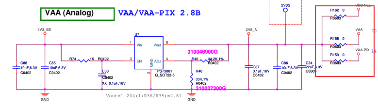
We try to change LDO to other solution ex: TPS73028 . There's no problem . Below is schematic and we want to know the reason why TPS736 have this problem but TPS730xx is OK ?
Many thanks !
 

  • Hi Terry,

    with -0.5V on the output it is possible the device was damaged since that is beyond the abs max voltage, though it doesn't seem very likely.  I have some questions which may help us determine what is happening.

    • Does the device operate at all after this happens?
    • Is the system trying to startup the LDO when the output voltage is still less than 0V?
      • Some devices won't start with the voltage pre-biased.
    • What is the voltage on Vin when this -0.5V is applied to the Vout pin?

    -Kyle

  • Hello Kyle,

    •Does the device operate at all after this happens? <= What device you mean ? TPS73601 ? If we try to reduce -500mV to around -100mV by reducing light for CMOS sensor. TPS73601 will work .
    •Is the system trying to startup the LDO when the output voltage is still less than 0V? <= En pin tied to VCC
    •Some devices won't start with the voltage pre-biased.<=Does TPS73601 can't output pre-bias and TPS730xx is OK ?

    •What is the voltage on Vin when this -0.5V is applied to the Vout pin?<=3.3Vin
  • Terry,

    see my responses in blue:

    •Does the device operate at all after this happens? <= What device you mean ? TPS73601 ? If we try to reduce -500mV to around -100mV by reducing light for CMOS sensor. TPS73601 will work . That answers my question, I wanted to determine if the device was damaged and no longer operational even under normal operating conditions. 
    •Is the system trying to startup the LDO when the output voltage is still less than 0V? <= En pin tied to VCC Ah yes I should have noticed that in the schematic, sorry. So it is starting up into the negative pre-biased voltage. 
    •Some devices won't start with the voltage pre-biased.<=Does TPS73601 can't output pre-bias and TPS730xx is OK ? It is important to note that -0.5V is beyond the abs max for this device but with that out of the way, every family of LDO's will handle negative pre-biases differently so I put the TPS73601 EVM on the bench and did some tests to find the limitations of the device.  The TPS73601 can start into a negative pre-bias but there are some limitations such as how far negative it is pulled and the amount of current the CMOS sensor forces into the output node. I found that if the voltage is more negative than -0.2V and sensor provides more than 500mA then the TPS73601 will not be able to overcome this negative pre-bias. If the voltage is between 0V and -0.2V then the TPS73601 can startup as long as the sensor does not provide more than the max current limit of 800mA. 


    -Kyle

  • Hi Kyle,

    Would you let me know more about Vout pre-bias spec ? Where we could see this spec ?

    Would you give LDO solution could meet Vo pre-bias below -0.3V ?

    Many thanks ~ 

  • Hi Terry,

    I am not aware of any of our positive voltage regulators which have an abs max lower than -0.3V.  I believe the device that has the best pre-bias (negative) performance is TPS7A83A but it is a 2A device and you are using a 400mA device. You could also try the TPS7A90 which is a 500mA device. It is important to note that exceeding the abs max voltage could damage the device so it would be best to address this in the application to minimize this negative voltage being applied to the output pin. 

    -Kyle

  • Hi Kyle,


    Because we find even the negative pre-biased voltage is -0.2 V, it also make the TPS73601 can't output.


    We compare the difference between the two LDO, is it the key of MOS type for negative pre-biased voltage or not?


    If yes , please help explain mechanism about it.


    Thank you!

  • Hi Kyle,

    Because we find even the negative pre-biased voltage is -0.2 V, it also make the TPS73601 can't output.

    We compare the difference between the two LDO, is it the key of MOS type for negative pre-biased voltage or not?

    If yes , please help explain mechanism about it.

    Thank you!

  • Hi Mike,

    It is very unlikely to be related to the type of FET used for the pass device.

    Both of these LDOs have fold back current limit which decreases the allowable current as the output voltage pulled down to lower levels. If pulled too low below ground some devices with fold back current limit set the current limit to 0mA which stops the device from being able to provide any current during Startup. The difference between the TPS736 family and the TPS730 family is the way the fold back current limit is implemented.

    -Kyle
  • Hi Kyle,

    Could we know the difference between TPS736 and TPS730 family about the chip design for this issue?

    Because we change the design to TPS730 family, we need to guarantee the part can work normally for our product.

    Thank you!


  • Hi Mike,

    As mentioned previously both of these devices have a foldback current limit which reduces the current as the output voltage is decreased. The way certain circuit blocks are implemented can change between various device families in order to achieve certain design goals which are targeted for certain applications. Thus the foldback current circuits of the two families of devices (TPS736 and TPS730) are not implemented in identical ways. Unfortunately, we cannot discuss the specifics of how the various circuits are implemented due to intellectual property concerns. I'm know that is an unfulfilling answer but we won't be able to provide those sorts of details.

    -Kyle