Part Number: BQ24650
Other Parts Discussed in Thread: CSD88539ND
Hey,
I have been trying to get a solar charger circuit working for the last one month. The circuit is based on the BQ24650 Solar battery charger. Even after multiple iterations of debugging I can't get it right.
I am using the input from a regulated supply right now set at around 21V with 2 Li-Ion cells in series with Vbatt upto 8.4V.
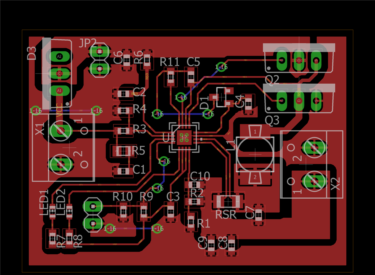
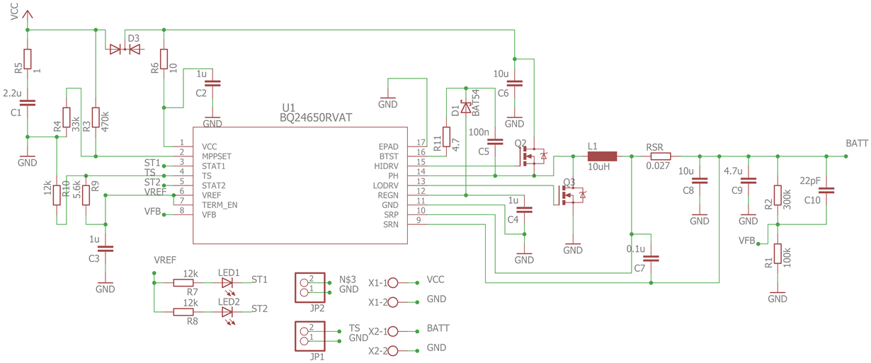
Here is the schematic and PCB layout:

Q2 and Q3 are P10NK602 which are rated at 600V, 10A
D3 is SBR1040CT
Following are the voltages at all the pins of BQ24650 while everything is connected including the battery:
1. VCC: 21V
2. MPPSET: 1.35V
3. STAT1: 1.9V
4. TS: 2.23V
5. STAT2: 1.9V
6. VREF: 3.3V
7. TERM_EN: 3.3V
8. VFB: 1.82V
9. SRN: 7.8 V
10. SRP: 7.8 V
11. GND: 0V
12. REGN: 0.62V
13. LODRV: 0V
14. PH: 7.8V
15. HIDRV: 7.8V
16. BTST: 7.5V
I think I have met all the requirements to enable charging. Please help me out and tell me if I can provide you with any other information that might be relevant.
Thank you,
Vivek


