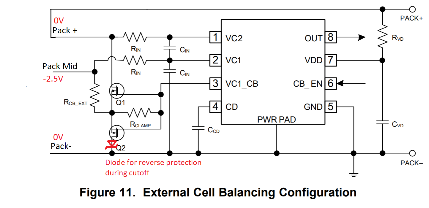
Hello, we are prototyping some battery management circuits that use a combination of an over/under voltage protection IC with the BQ29200 for cell balancing on a 2S 18650 LIPO pack. We are effectively using the circuit in figure 11 of the datasheet. One issue we are having though is that when the under voltage cutoff IC trips, it uses a low side FET cutoff, so that Pack+ and Pack- become 0V, (due to the load on the pack pulling pack+ to pack-) but the mid cell input into VC1 stays more negative than both of them (about -2.5V). This is a direct violation of the BQ29200 datasheet. Is this likely to cause a problem? Are there clamp diodes on this input that would cause current to flow from the -2.5V mid cell voltage to the Pack- voltage?
We have also added a shotkey diode to the low side balance FET to block that reverse path.
Our other option would be to move the BQ29200 to the pre-undervoltage cutoff side of the pack, which would keep the cell voltages at proper levels in relation to each other, with the negative effect of the BQ29200 IC consuming it's Icc supply current and VC2 input consumption current would in theory damage the cells over time. This should be approx 3uA + 2.5uA = 5.5uA, which would then take over a year to drain 100mAH from a battery, which seems acceptable. Is connection of this IC to bare un-protected cells the typical recommended design?
Thank You!


