This thread has been locked.

If you have a related question, please click the "Ask a related question" button in the top right corner. The newly created question will be automatically linked to this question.

LM2776: Sometimes the output is not correct (not the expected -5V but around -1.3V).

Part Number: LM2776
Other Parts Discussed in Thread: OPA4188, , LM4040

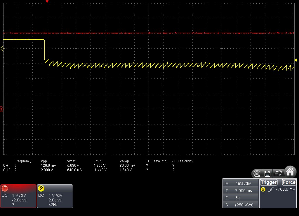
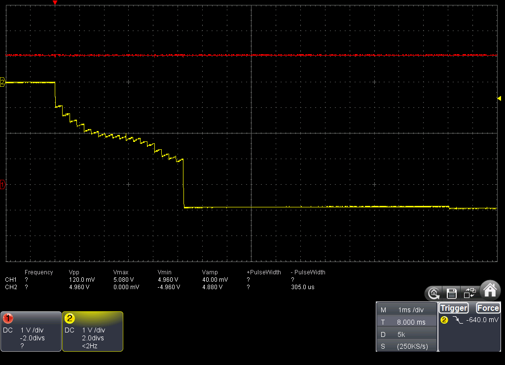
In a prototype PCB I have a linear power supply (120V to 12V then a LDL1117-5V regulator) that power the LM2776. The load are multiple OPA4188 amplifiers with a +5 and -5 supply. At startup, when using AC mains, *sometimes* the output of the LM2776 does not reach -5V but stay oscillating around -1.3V. If I use a battery to power the linear regulator directly, the problem always happens.

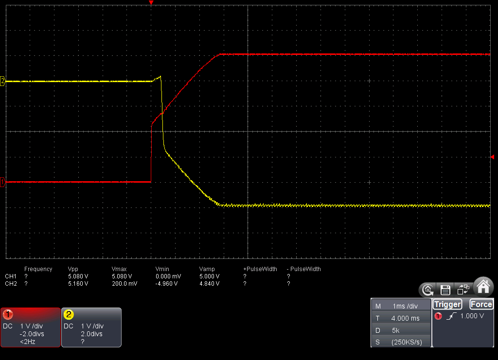
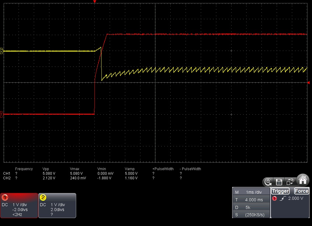
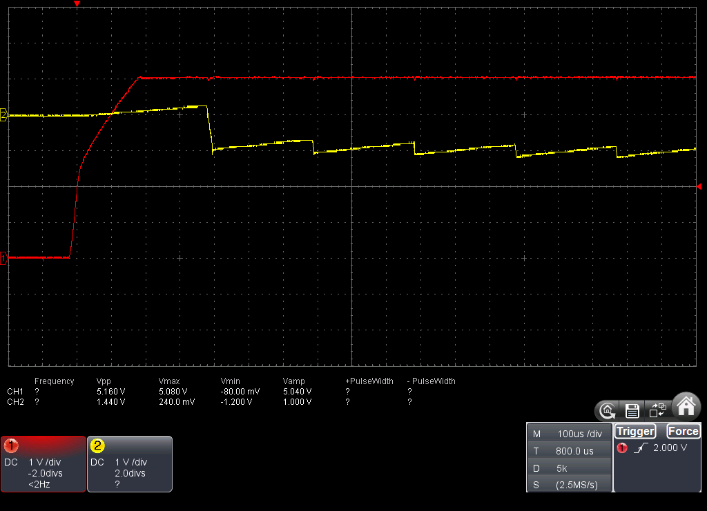
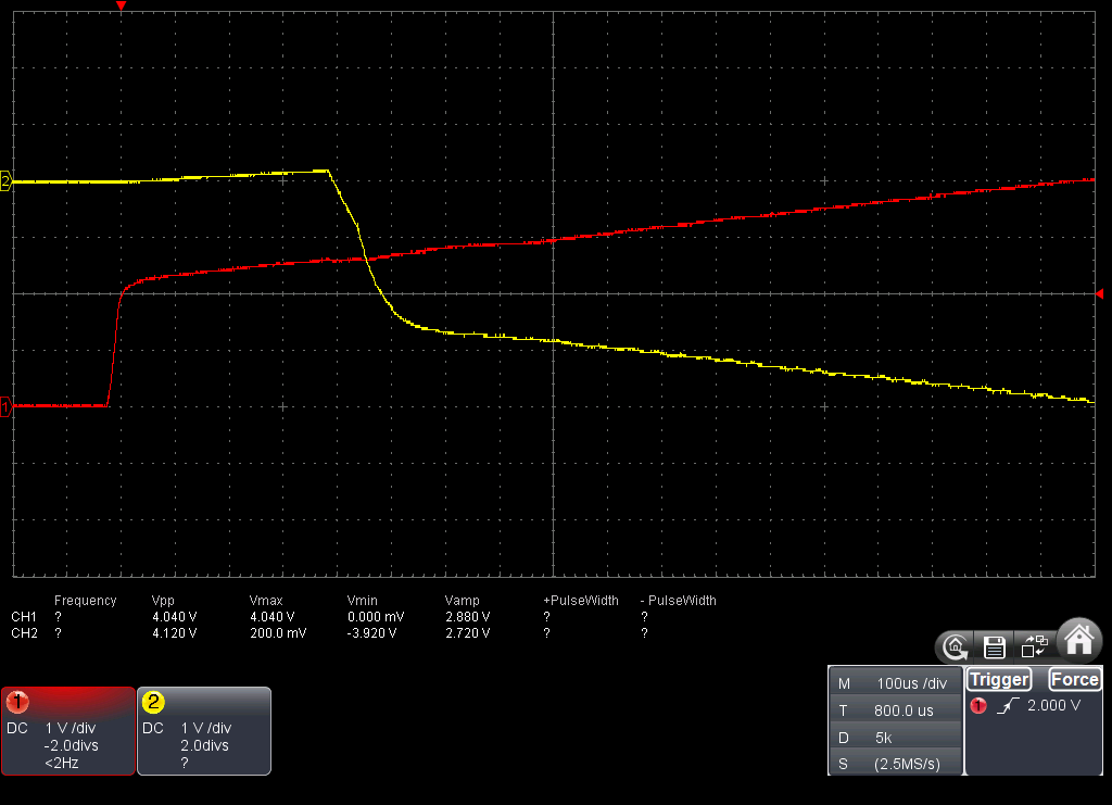
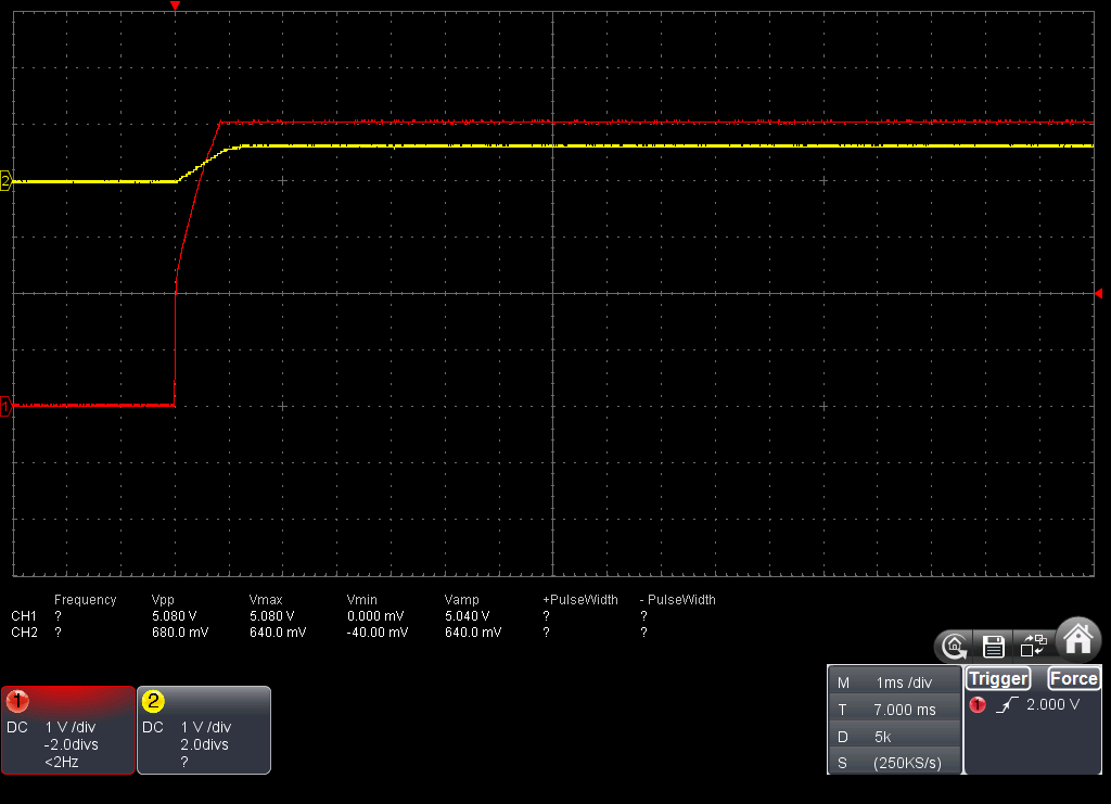
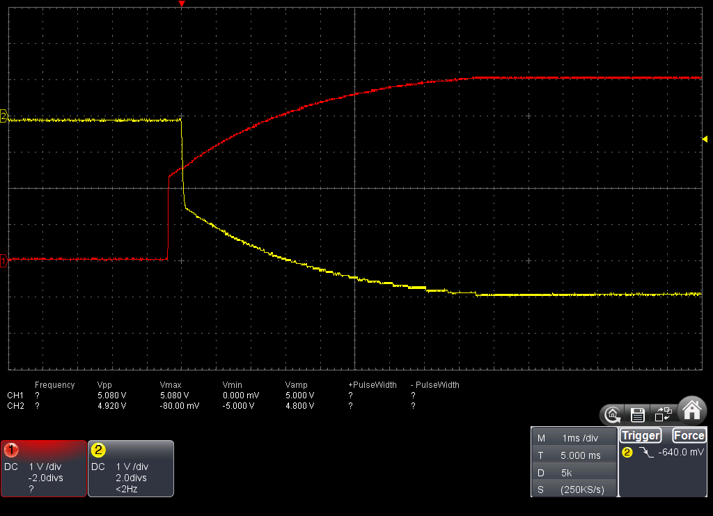
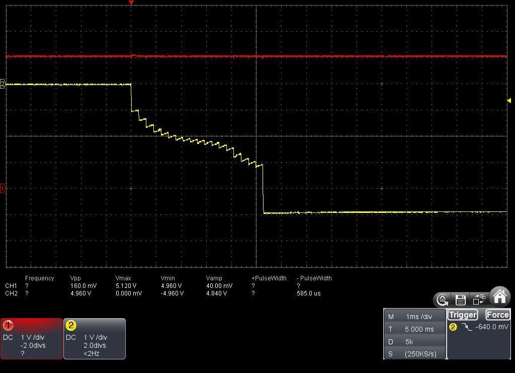
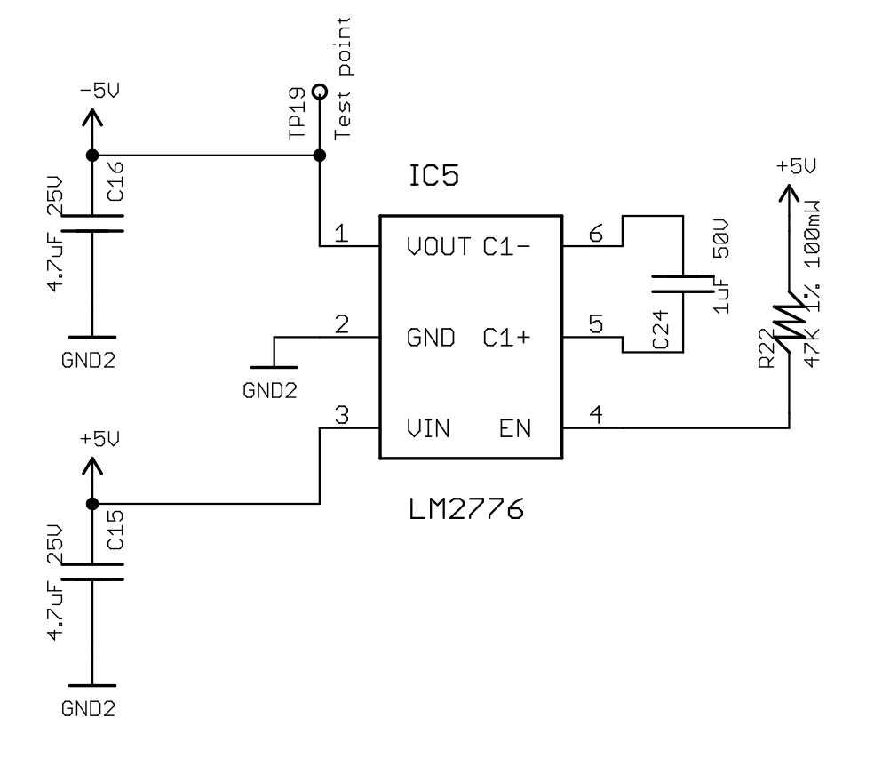
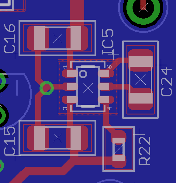
This is the schematic, PCB layout and Vin / Vout signals:

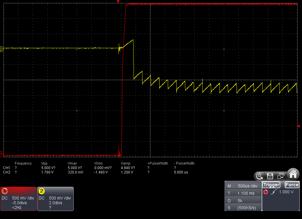
I don't know if this a layout issue or if the positive voltage in Vout before the LM2776 is enabled may cause this. The only difference I can see between a failed startup and a successful one is the slope of the linear regulator output voltage (depending at what time of the 60Hz AC cycle is turned on, its output voltage raise faster or slower).

In case it matters, the following are the component parts:

Parts Value MF MPN
C24 1uF 50V X7R 10% Murata GRM31MR71H105KA88K
C15, C16 4.7uF 25V X7R 10% Murata GRM31CR71E475KA88L
R22 47K 1% 100mW Yageo RC0603FR-0747KL
IC5 LM2776 Texas Instruments LM2776DBV

Any suggestion is welcome. Thanks in advance.

  • Hello,

    I have a some questions:
    Can confirm that CH1 of the scope plot shows the input voltage VIN and did you probe at VIN pin (pin 3) of LM2776?
    Is there a load connected already at start-up and what kind of load?
    Could you please also provide a scope plot of a successful start-up.

    Thanks.
    Best regards,
    Ivo

    Texas Instruments
  • The CH1 plot is the input voltage, but it was probed at a test point a few millimeters away from the VIN pin of the LM2776. If this is important, I can test again probing directly the VIN pin.

    The load contains three OPA4188 op amps (+5 and -5) and a DG408 multiplexer (+5 and -5), also (powered only by +5V) a microcontroller, FRAM memory, USB-UART bridge (unconnected during tests), and two LM4040 references. During the tests all external inputs connected to the amplifiers were connected to ground.

    The following are the plots of the device when powered from AC mains (all successful). I also included again a failed one when powered with a battery, using the same scale (for comparison).

    Thanks in advance.

  • Hi Mario,

    Thanks for sending the waveforms. Can you zoom in to maybe 100 usec/div on the time when Vin is applied? It is difficult to tell the differences in the Vin signal between these 4 waveforms.

    As well, does it help if EN is held low until Vin is fully up at 5V? i.e. can you GND pin 4 with tweezers and then release it, after Vin is at 5V?
  • Hi. These are zooms of two failed startup:

    This is the zoom of a successful one:

    If a hold the EN pin low until the 5V input is fully on, the LM2776 always fail to start correctly. Also, the negative rail raises up to 640mV while EN is low. My guess is that there is current flowing from the load. The following are two waveforms, when the positive rail gets to +5V while EN pin is low and what happens when enable the LM2776.

    Thanks in advance.

  • Thanks for sending. Yes, we need to prohibit the positive voltage applied to your load from bleeding onto the negative rail through the load.

    If you disconnect the positive voltage from your load, does the negative voltage always start correctly?
  • Hi. Yes, if I disconnect the load from the supply the LM2776 starts correctly, at the same time the positive rail raises or later if I delay the EN pin.

    So, Is safe to assume the positive voltage in the output of the LM2776 is causing this?

    Thanks in advance.

  • Yes, it is recommended to prohibit a positive voltage from appearing at the output of a negative voltage converter.

    But even the above startup waveform looks ugly. It looks like the load is too high. Can you measure the output current (current after C16) in the above waveform?
  • Hi. For that test there was no load on the LM2776 and also there was no load on the positive rail.

    Yes, if I apply power to the LDL1117 that feeds the LM2776, it starts almost symmetricaly. But if I delay the EN signal the LM2776 starts at a slower pace. Both tests were done without load. Even if I bypass the positive LDO and apply 5V directly to the LM2776 while delaying the EN signal, it starts slower.

    I'll populate another PCB with only the power supply and another with only the LM2776 to continue these tests. I'll let you know what I find. Of course any extra idea you may have is welcome.

    Regards and thanks.