This thread has been locked.

If you have a related question, please click the "Ask a related question" button in the top right corner. The newly created question will be automatically linked to this question.

TL494: Voltage drop @ full load in Buck Converter

Part Number: TL494

Hi,

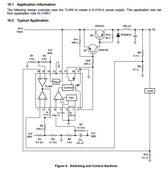
I have made a buck converter based on the circuit in tl494_TI datasheet. These are design parameters:

Vi=58 V,    Vout=48V,    I_load=10A      

TIP42 and 2*TIP35C are used instead of NTE153 and NTE331 respectively.

I have 2 V voltage drop @ 10A! 

What the problem might be? Different chokes show the same drop and it is scaled in load change.(.e.g 25V 10A >> 1V drop or 48V 5A >> 1V drop)

  • Hi Mohammad,

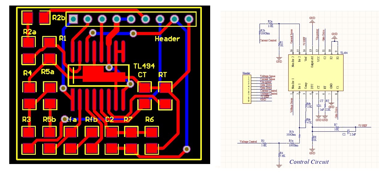
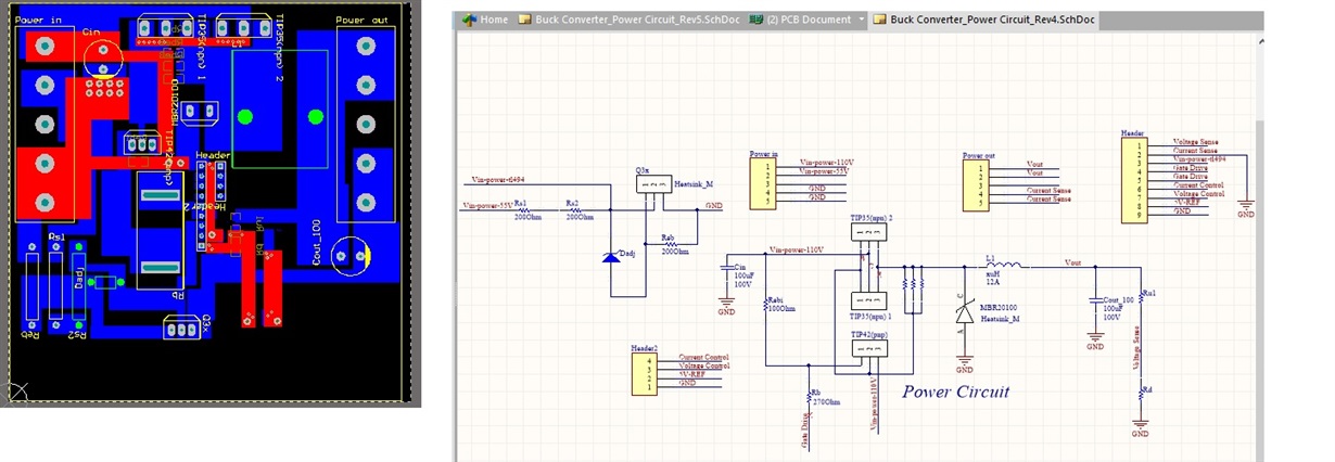
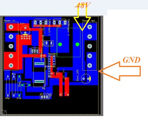
    Thanks for your interest in TL494. Are you able to attach an image of your test setup? can you share your schematic and layout?

    Best Regards,
    Ben Lough
  • Hi Mohammad,

    Where on your pcb are you physically measuring the output voltage? Can you measure directly across your output cap?

    Best Regards,
    Ben Lough
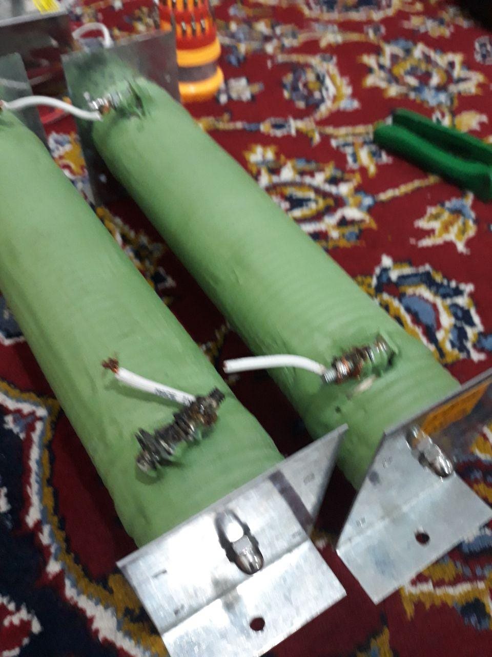
  • I use 4.8 Ohm /1kw resistors @ the output (connected via wire size: 1.5) but I measure voltage right @ the terminals. This is the first version...and I have tried larger inductors with/without gap...ferrite and iron powder...in different sizes...all of them show almost the same result...It seems voltage drop is scaled over load change(0-10A) 

  • Hi Mohammad,

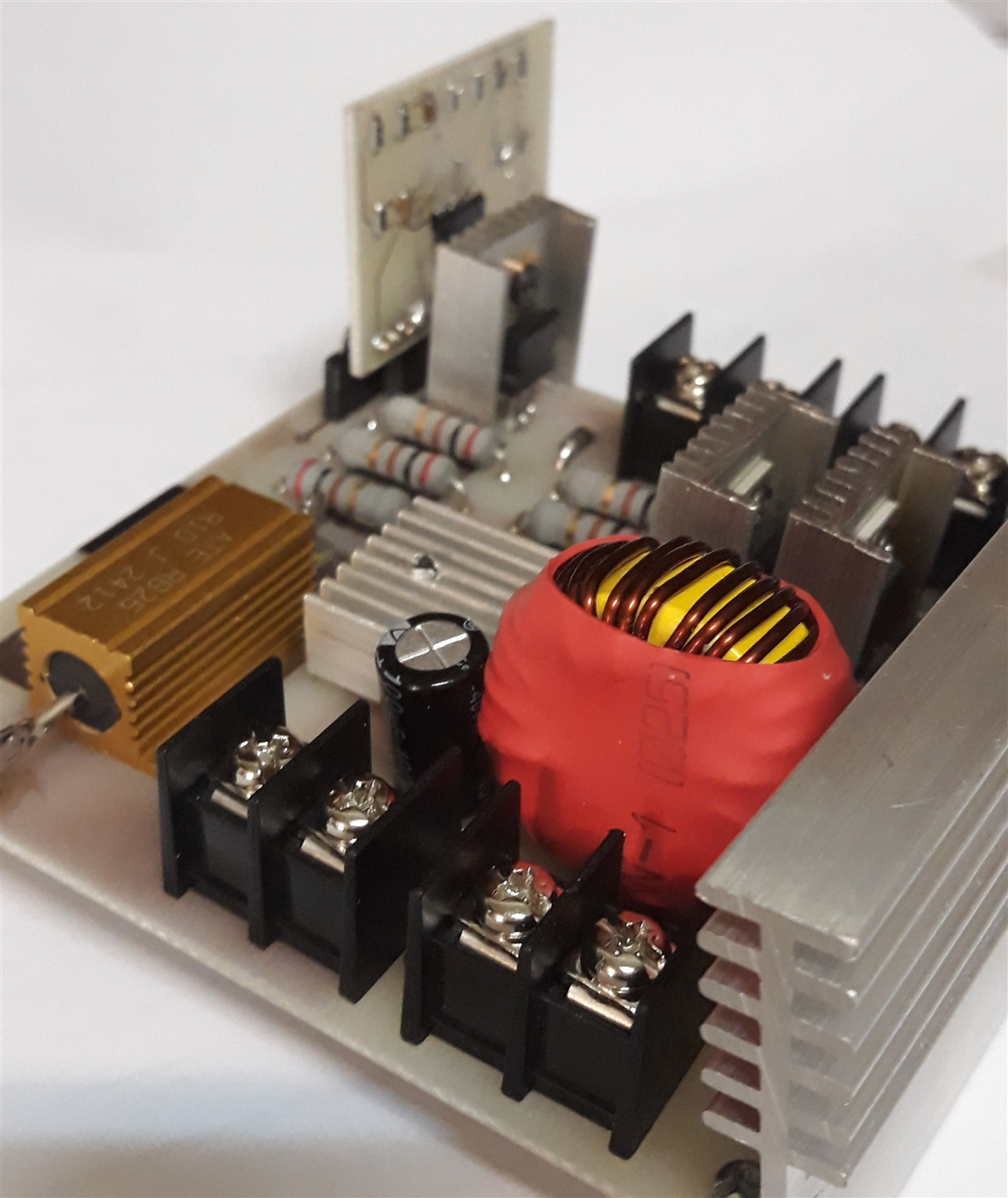
    Thanks for the images. I would suggest connecting the top of your feedback network (Ru1) directly to your output terminal instead of through the trace. The image of your board looks different from the altium layout you shared. The output cap is beside the output terminals in your layout but in your image it appears to be behind the output terminals for instance. Do you have multiple board versions?

    Best Regards,
    Ben Lough
  • Thanks for your exact examination
    Yes, the board related to that PCB is not available right now. I'll upload that after weekend...I'll also try that tip you mentioned about layout and Ru1, but there's a question . Is that for the voltage drop between terminal to feedback resistor, Ru1?! Because in that case feedback voltage will be lower then the loop tries to enlarge PWM width. So Vout will be higher...

    Are the transistors suitable to be used instead of  NTE types?
    (NTE331 >>> TIP35C                NTE153 >>> TIP42)

  • Hi Mohammad,

    Its just a check to see if conduction losses along the trace from the inductor to the output terminal is factoring into the voltage drop. Typically you want the feedback network to connect to the output voltage at the desired point of regulation (in this case, the output terminal).

    Other things I would check
    1. Make sure your input voltage is 58V at full load. Measure the input voltage directly on your board, not the power source
    2. Check the voltage at pin 1 of TL494 and make sure it matches your reference voltage (voltage_control * the divider formed by R3 and R4).
    3. Check your duty cycle on an oscilloscope and make sure it is consistent.

    By the way, what is your voltage regulation requirement?

    Best Regards,
    Ben Lough
  • Hi,
    I checked those parameters you mentioned (In full load, Vo=48 and Rout=5 Ohm):
    -58V becomes 57.7
    -Both pins of error amp (1 and 2) have the voltage 2.35 instead of 2.56(in full load condition)
    -Duty cycle is not enough. It's 83.3. Assuming 2V for saturation voltage of TIP35C, we have Vo=(57.7-2)x0.833=46.4 and that is almost delivered at the output terminal.
    I also tried connecting feedback node directly to Vout but it didn't help.
  • Hi Mohammad,

    This suggests there is an issue with the voltage control signal. Is this signal dipping at full load?

    Best Regards,
    Ben Lough
  • Hi,
    Yes. Two pins of TL494 , number 1 and 2 will drop from 2.5V to 2.3 V in full load(10A).

    As I said before in 5A there is a voltage drop half of that in 10A, approximately.

  • Hi Mohammad,

    Is the voltage of Voltage Control dipping as you increase the load (not at the TL494 pin but at the source of Voltage Control)? How are you generating the voltage control signal?

    Best Regards,

    Ben Lough

  • In first tests I connected Voltage Control to 5Vref pin, but I have to see if it goes down under load condition.
    In main case, Voltage control pin is controlled bya DAC IC and micro controller and this showed same result.(Output Voltage drop)
  • Hi,
    Output voltage is digitally controlled via AVR microcontroller. We set a voltage and voltage control is produced from a DAC IC.

    Does it have any problem if I compare Setup voltage and the voltage measured with ADC then force the voltage control to rise up till it reaches to desired value?