This thread has been locked.

If you have a related question, please click the "Ask a related question" button in the top right corner. The newly created question will be automatically linked to this question.

BQ76930: Problem with voltages of Cells 1-3/ Balancing fets

Part Number: BQ76930


Hi there,

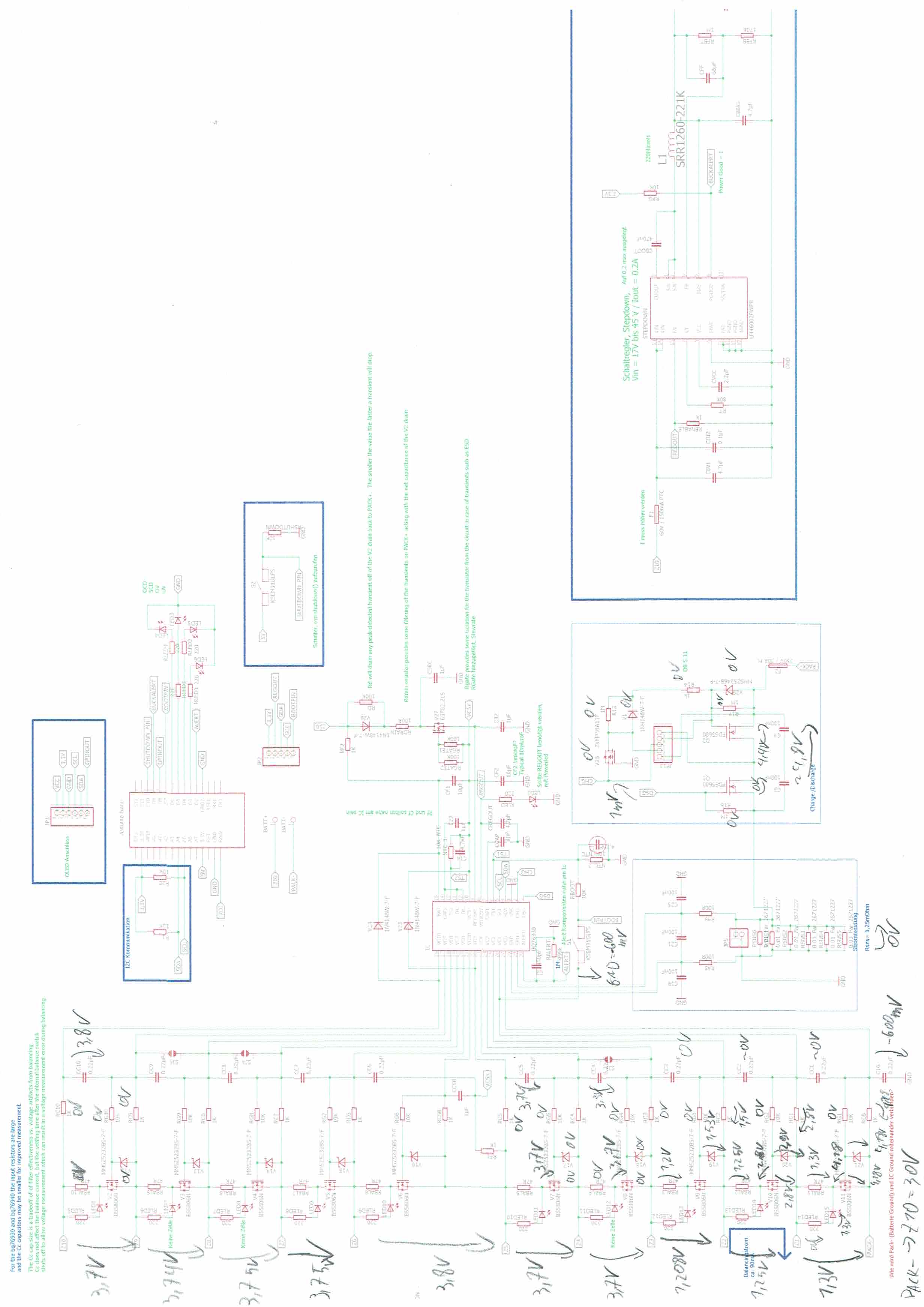
well i've designed a pcb for 7-10 Cells using the BQ7693003. I use an Arduino Nano to read/set the registers of the IC. That works perfectly. 

My problem is, that after a short period of time ( like 1-2 sec) i'll get an UV Error. To emulate the Cells i use 10 x100Ohm resistors in series connected to 30V. I also use n-fets for external balancing and implemented LEDs in parallel to the balancing resistor.

Somehow my Cellvoltage of Cell 1 -3 are not acurate because the mosfets of those cells are enabled( other cells compensate the voltage differents). The Cellball registers of the IC are all set to 0, so i can't figure out why the fets are enabled.

I think my ground connection might have some errors.

Here you can find my shematic:

I measured some Voltages, which might help figuring out the problem. ( i hope you can read my handwriting)

Thanks in advance!!!

Kind Regards, 

Alex

  • Hi Alexander,
    The schematic topology looks basically correct but the RC0 and V11 source should connect to battery negative rather than PACK-. You will know your schematic better but it appears the battery negative is GND which would carry the load current (coming into PACK- through the FETs and to the sense resistor) from the sense resistor back to the battery through your PACKCONNECTION connector. PACK- is the load side of the battery system (connected to Q2) and may be pulled up to cell10 voltage with the discharge FET off. Compare to figure 8-2 of the data sheet. I'm not following all your voltage notes but the connection shown would result in improper voltages to the bottom inputs of bq76930 and the related circuitry.
    Once you make the proper connection check for proper operation of the components. The balance FET gates should have been protected by the zeners and current would be limited into the bq76930 pins by the resistors, but parts may have been overstressed.
    Also be cautious of the battery negative current in the GND connection. While the various GND points should all connect, be cautious of forcing different voltages due to the battery current, see figures 10-2 and 10-3 in the bq76930 data sheet.
  • Hi WM5295, thank you for your quick answer.
    I'm not sure, if i understand the first part. What is the difference between battery negative and Pack-? ( As you mentioned, i've connected RC0 and V11 to the battery negative)

    I'm now 100% certain, that the ground connection is the problem. I've build up a 2. pcb, this time i didn't solder on the CHG/DSG circuit and everything works fine(TS1 now messures correct temps).
    Do get the CHD/DSG circuit working, do i have to swap the inputs of that circuit maybe?
    Kind regards, Alex
  • Hi Alexander,
    I used the term "battery negative" to mean the most negative potential of the cell assembly. Sorry for the confusion. In the bq76930 data sheet figure 8-2 that connection is shown with a ground symbol but no specific net name, and connects both to the sense resistor and RC0.
    In your schematic the left side of the sense resistor is GND, and is supported on the PACKCONNECTION connector. PACK- is connected to F2, the output of the battery assembly or battery unit, this is your protected negative terminal of the battery system. However the PACK- net name is also shown connected to RC0, V21 and V11 which should be "GND". I suspect that sub-net connection is the ground problem.
    To attempt to answer your question next to C16, the most negative of the cells should connect to RC0, V21, V11 and GND (including the left side of the sense resistors). PACK- is connected to the IC ground and to the cell stack negative through the sense resistors by the Q1 and Q2 FETs when they are on.
    You will know your schematic, board, and cell connections better. I hope this helps.
  • Thank you very much, that helped my a lot!