This thread has been locked.

If you have a related question, please click the "Ask a related question" button in the top right corner. The newly created question will be automatically linked to this question.

UCC28881EVM-680: 230Vac to 5Vdc/400mA

Part Number: UCC28881EVM-680
Other Parts Discussed in Thread: LM25007, UCC28881,

Hi,

I'm designing a power supply that should deliver 3.3V and 5V from 230VAC. The current rating is 300mA @ 3.3V and 100 mA @ 5V (Maximum values).

My biggest concern is that i have a small area to design my board, so i have to make my design similar to the UCC28881EVM-680 power supply board and the DC-DC buck regulator LM25007 like this one http://www.ti.com/lit/ug/snva152a/snva152a.pdf,

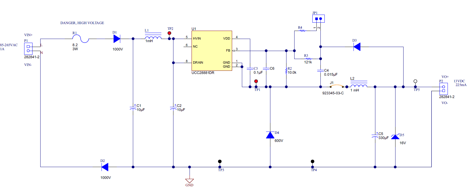
So the idea is convert the 230VAC using the UCC28881 in order to obtain 13VDC/225mA which is equal to a power of 2.9W, and then i have to use another DC-DC buck regulator to drop down the 13V to 5V using the LM25007.

I can't use a linear regulator otherwise i can't obtaint the 400mA current to feed the 5V and 3.3V components.

The 400mA needed from ther 5V is divided in two part, the first 100mA will feed the 5V circuit and the 300mA will feed a 3.3V regulator in order to obtain 3.3V 300mA.

1/ i want to know if the idea/schema is correct ? Can the output of the UCC28881EVM-680 feed correctly the LM25007 DC-DC converter ?

2/ as i told in the begining that i have small area to design my power supply, so i have to revise some components size from the UCC28881EVM-680 and i want to know if it still correct.

2-a/ the capacitors :

both input capacitors C1 and C2 'EEUED2W100' in the design are too big so i change them to this capacitors 860241375002 which is thinner. they have the same capacitance as the one in the design but the rated voltage of the new one that is only 400V compared to 450v form the design.

I think 400 is good enough for 230VAC ?

About the output capacitor C5 'EEU-FM1V331L' i change it for this smaller one '25SEPF330M'.

It has the same capacitance but with lower voltage, Only 25V. I think is enough for the output voltage that can climb to 16V ?

and the new one has a smaller ESR 'equivalent series resistance' only 14 mohm compared to the original one which is 30mohm. So this is a good things knowing that the lower ESR the lower the voltage output ripple ?

i want to know if i can lower the capacitance of both input/output capacitors? if yes, how much can i decrease ?

3-b/ inductors :

input inductor L1 ; i changed the 5800-102-RC model with this one ELC09D102F.

output inductor L2; i want to know why the current satruation is chosen as 400mA knowing that the output max current is 225mA ?

can i choose another one with lower current saturation? 

Is one of these are good for this application :
- 744772102 : RMS Current (Irms): 300mA , Saturation Current (Isat): 500mA

or this one DR0608-105L :RMS Current (Irms): 400mA , Saturation Current (Isat): 350mA

3-b/ Fuse :

i want to replace the big resistor used as a fuse with a PPTC Resettable Fuse like this one 'LVR012K' ?

Is the holding current of 120mA is enough ?

Because the maximum input power is 3.581W for 230VAC which is equal to a current of 15mA

3-d/ can i remove the resisor R4 connected to the feedback FB pin of the UCC28881 chip ?

Thanks you,

  • Hey Chamkhi Haithem,

    You've got a good amount of questions, I'll format my reply in a Questions Answer format to help keep things clear!

    Q: 1/ i want to know if the idea/schema is correct ? Can the output of the UCC28881EVM-680 feed correctly the LM25007 DC-DC converter ?

    A: This kind of schema is fine and TI has a reference design with a similar idea in mind here: www.ti.com/.../PMP11236

    The power outputs are different but the schema/idea is similar to what you're going for.

    Q: I think 400 is good enough for 230VAC ?

    A: Yes, you can use 400V rated capacitors for 230VAC.

    Q: It has the same capacitance but with lower voltage, Only 25V. I think is enough for the output voltage that can climb to 16V ?

    A: That should be fine, but you can double check the manufacturer's datasheet to find the derating of the capacitors for the voltages and see how the capacitance is affected.

    Q: i want to know if i can lower the capacitance of both input/output capacitors? if yes, how much can i decrease ?

    A: You can follow the calculations used in the datasheet for the UCC28881 to find the equations used to calculate input bulk and output capacitance. Follow the implementation here: www.ti.com/.../application_and_implementation

    Q: can i choose another [inductor] one with lower current saturation?

    A: Inductor selection is dependent on the output ripple current on the inductor as well as the rms current. Follow the implementation as shown in the datasheet (previously linked) to determine inductor parameters for your design.

    Q: i want to replace the big resistor used as a fuse with a PPTC Resettable Fuse like this one 'LVR012K' ?

    A: That fuse is used to limit in rush current as well as provide safety to the design in case of emergencies. I would advise keeping this.

    Q: can i remove the resisor R4 connected to the feedback FB pin of the UCC28881 chip ?

    A: That resistor, if the jumper is connected, is used to change the output voltage by changing the feedback network. So you can remove it if you already have a set of resistors for your design and do not need to do testing or component swapping.

    Hope this answers your questions!

    Regards,

      Davit

  • THANKS FOR YOURR ANSWER I APPRECIAT THAT,

    one last things that bother me is the output inductor. i had to choose this one which is smaller DR0608-105L ,it has the same inductance of the design which is 1mH , but the current saturation is lower and only 350mA. 

    and from what i read in the documentation that you provided me,  the worst case the ILimit is about 315mA which is above the current saturation.

    regards,

  • Hello,

    The inductor you chose is rated for 300mA, and at 350mA there is a 10% drop in inductance. That means your inductor value is now 0.9mH under those conditions. I looked at the datasheet calculations and the inductor needs L > 536uH. It seems like your inductor selection may be fine.

    This is assuming that your output is the same as the EVM/Typical Application: 13V. If not, you need to redo your calculations with the desired output voltage.

    Regards,
    Davit