This thread has been locked.

If you have a related question, please click the "Ask a related question" button in the top right corner. The newly created question will be automatically linked to this question.

TPS7A30-49EVM-567: TPS7A3001 output does not equal programmed output

Part Number: TPS7A30-49EVM-567
Other Parts Discussed in Thread: TPS7A30

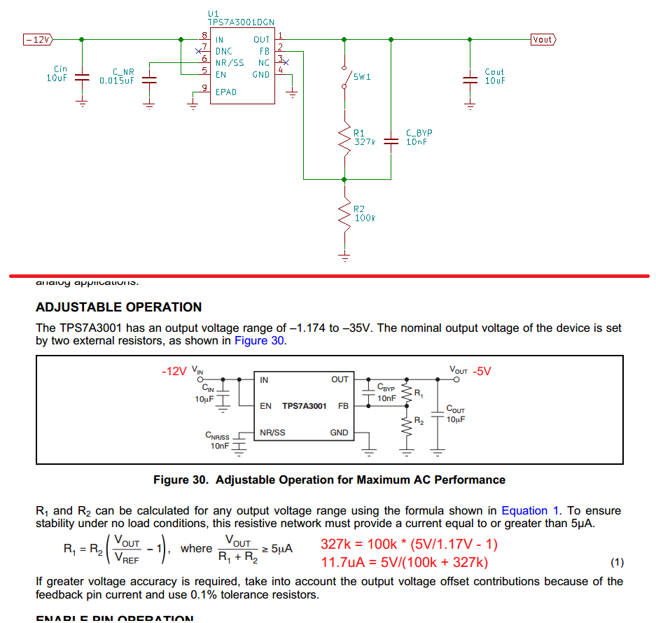
A TPS7A3001 is wired for a -5V output.  R1 and R2 are selected to achieve a -5V output.  However, Vout equals -3.9V instead of -5V.   

When SW1 is opened, the output changes to -12V from -3.9V.  However, when S1 returns to closed, Vout changes to -5V instead of back to -3.9V.  Is there criteria besides a resistor ratio and resistor current for correct operation?

  • Hi Jeff,
    Your input/out voltages and feedback resistor values properly set for correct operation.
    May I ask why you have a switch on the feedback network?
    As for Vout not reaching its set point when you power on the device and the switch is on, can you check to see if your C_BYP capacitor is leaking or not by removing it and powering the device on and report back?
    Also sometime unintentional flux between the device's pin could cause Vout not to reach its set value.
    BR,
    Haidar
  • Haidar,

    Switch SW1 does not exist in the circuit.  The switch is schematically shown to convey the sequence and behavior of the circuit. The value of the C_BYP is 10nF. 

    C_BYP is supplied from the TPS7A3001demo board.  The demo board is part TPS7A30-49EVM-567.  There is no flux residue around the regulator, C_BYP, R1 and R2.  

    R1 and R2 on the demo board TPS7A30-49EVM-567 have been replaced with 327k and 100k and the regulator continues to start at -3.9V.  All other parts are unchanged on the demo board.  Do you have access to a TPS7A30-49EVM-567 to repeat the behavior?

  • Hi Jeff,
    Thank you for the additional information, I have ordered the EVM and will replicate your feedback resistor setting and do some testing as soon as I get it.

    Best regards,
    Haidar
  • To reproduce the incorrect output voltage from the regulator using the TPS7A30-49EVM-567 demo board -

    - Install a 327k resistor at R1

    - Install a 100k resistor at R2

    - Install a 1k resistor between -Vout and GND.  This provides a 5mA load.

    - Turn on a bench power supply and set it to -12V.

    - Attach the power supply to -Vin.  This will eliminate any differences between our power supply turn on ramps.  What do you get for -Vout?

  • Jeff and Hiadar,

    I think I have similar issue with two TPS7A30-49EVM-567 boards that were bought recently :
    They should come pre-configured to 15V +Vout and -15V -Vout. My eval units simply mirror the input voltage regardless of the R1/R2 and R3/R4 ratios.
    When I change R3 to a 0 Ohm jumper and remove R4, +Vout goes to about 1.2 V meaning that internal references is generated correctly.
    When I put the jumper to OFF position, the voltage goes down in all configurations.

    The other board that I bought a couple months ago works perfectly. The new boards don't show any indication of residue flux or other soldering issues.

    Thanks,
    Ruslan
  • Ruslan,

    I tested the positive regulator section on my TPS7A30-49EVM-567.  That is, the TPS7A4901.  The board is Rev.A

    • No changes or modifications to the board from the factory.
    • Place the enable jumper to ON
    • Apply a 1k resistor between +Vout and GND for a 15mA load
    • Apply +18V to +Vin.

    The result is +15V at the output +Vout.

  • Hi Jeff and Ruslan,
    I got my EVM set Rev.A and did a quick check right off the box, I have verified the output to be +15V and -15V for +18V and -18V input respectively.
    Then I change the feedback network in the TPS7A30 similar to Jeff's setting with the 1k resistor at the output and -12V at the input but the output read -5V not 3.9V and I could not replicate what Jeff saw.
    As for my recommendation for the bad boards, you can check to see if you guys can get replacement from the store you bought the boards from.
    Best regards,
    Haidar