Hi,
I am seeing an issue where the TPS61201 appears to draw too much current from the input in some cases.
I have the device in Power Save mode (PS = LOW).
At 1.5v input, I see the problem.
At 3.0v input, I do not.
I have spent a while trying to understand what's going on here. The measurements are so far out from what I'd expect that I'm assuming I'm doing something wrong, but can't figure out what it is. Help would be appreciated!
My question appears to be very similar to another unresolved forum post (link). I read that post, and many datasheets and application notes, have attempted to provide all the detail needed here. Please let me know if I can provide anything else.
I have a resistor-only load and am able to compare expected regulator input/output values to actuals.
Below I outline the expectations/measurements for two test scenarios
- 1.5v input voltage to the regulator, a 50Ohm resistor load
- 3.0v input voltage to the regulator, a 50Ohm resistor load
In both cases I'm expecting the output voltage of 3.3v and output current of 66mA for the 50Ohm load.
At 1.5v, I'm expecting an input current of ~181mA. But I see 550mA. That's almost 3x.
At 3.0v, I'm expecting an input current of ~90mA, and I do, so that is ok.
The way I'm calculating my expectations is:
- total output current (3.3v / 50Ohm) = 0.066A
- total output power (3.3v * 0.066A) = 0.2178W
- input wattage at regulator efficiency of 80% = (0.2178 / .8) = 0.27225W
- input current at 1.5v = (0.27225W / 1.5v) = 0.1815A = 181mA
- input current at 3.0v = (0.27225W / 3.0v) = 0.0907A = 90mA
I will note that I followed the "Performing Accurate PFM Mode Efficiency Measurements" (link) Application Note when doing measurements.
This involved putting a large cap across regulator input for measuring, which made a negligible difference, doesn't explain large current draw measurement differences from expectation. The AN indicated measurements could be off by upward of 15% if done incorrectly, which is well below the error I'm seeing of nearly 3x. So this does not appear to be an explanation.
Here is the way the regulator is wired:
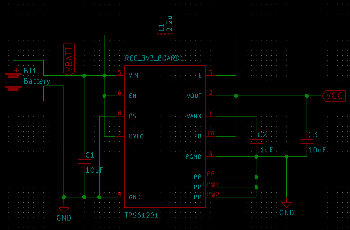
For the tests below, this regulator is isolated from all other components except the power supply and load, as described later.
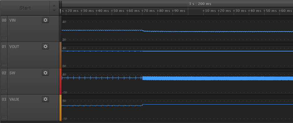
The previous forum posting there was a request for measurements of VIN, VOUT, SW, VAUX.
I have provided them below for the 1.5v case and 3.0v case.
I'm taking SW to mean pin 3 (L). If that's wrong please let me know.
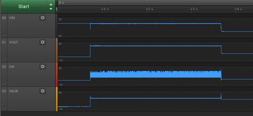
First set of measurements - 1.5v input
Measuring VIN, VOUT, SW, VAUX.
Measuring Power Supply current, load current.
I measured 3 states:
-
#1 - Initial state, power supply on, regulator not connected to power supply
-
#2 - Power up regulator, no load (at 750ms in timeline)
-
#3 - Attach load to regulator (at 3 sec 750ms in timeline)
State #1:
-
VIN - 1.5v
-
VOUT - 0v
-
SW - N/A
-
VAUX - N/A
State #2:
-
VIN - 1.5v
-
VOUT - 3.3v
-
SW - (see screenshot)
-
VAUX - 3.6v
State #3:
-
VIN - 0.5v
-
VOUT - 0.9v
-
SW - 0.3v (flat)
-
VAUX - 3.1v
In state #3 the power supply was providing 550mA and load current was 18mA.
This does not match my expectation.
Here are screenshots of the measurements on a scope.
State #1, #2, and #3 in one view:
Transition between state #1 and state #2:

Transition between state #2 and state #3:

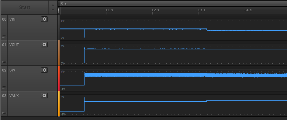
Second set of measurements - 3.0v input
Measuring VIN, VOUT, SW, VAUX.
Measuring Power Supply current, load current.
I measured 3 states:
-
#1 - Initial state, power supply on, regulator not connected to power supply
-
#2 - Power up regulator, no load (at 500ms in timeline)
-
#3 - Attach load to regulator (at 3 sec 250ms in timeline)
State #1:
-
VIN - 3.0v
-
VOUT - 0v
-
SW - N/A
-
VAUX - N/A
State #2:
-
VIN - 3.0v
-
VOUT - 3.3v
-
SW - (see screenshot)
-
VAUX - 3.5v
State #3:
-
VIN - 2.9v
-
VOUT - 3.3v
-
SW - (see screenshot)
-
VAUX - 3.8v
In state #3 the power supply was providing 87mA and load current was 62mA.
This does match my expectation.
Here are screenshots of the measurements on a scope.
State #1, #2, and #3 in one view:
Transition between state #1 and state #2:

Transition between state #2 and state #3:
Final Thoughts
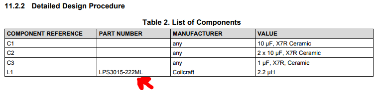
The only other lingering thought I have is that the inductor I used is somehow wrong, but I really don't understand the underlying principles well enough to guess.
I have a 2.2uF 0603 SMD inductor, which I also tried replacing with a through-hole version, and saw no measurable difference.
I had doubts because I looked at some other designs using the TPS61201 which used a different and physically larger inductor with a larger footprint, though still 2.2uF.
If that is somehow a factor I'd be interested to hear about that as well, but I feel like that's grasping at straws.
Thank you.
doug