This thread has been locked.

If you have a related question, please click the "Ask a related question" button in the top right corner. The newly created question will be automatically linked to this question.

TPS61201: Unexpectedly high (3x) input current at 1.5v in Power Save mode

Part Number: TPS61201

Hi,

As referenced in the other thread, I did use the LPS3015-222MRB power inductor and the issue was lessened, but not resolved.

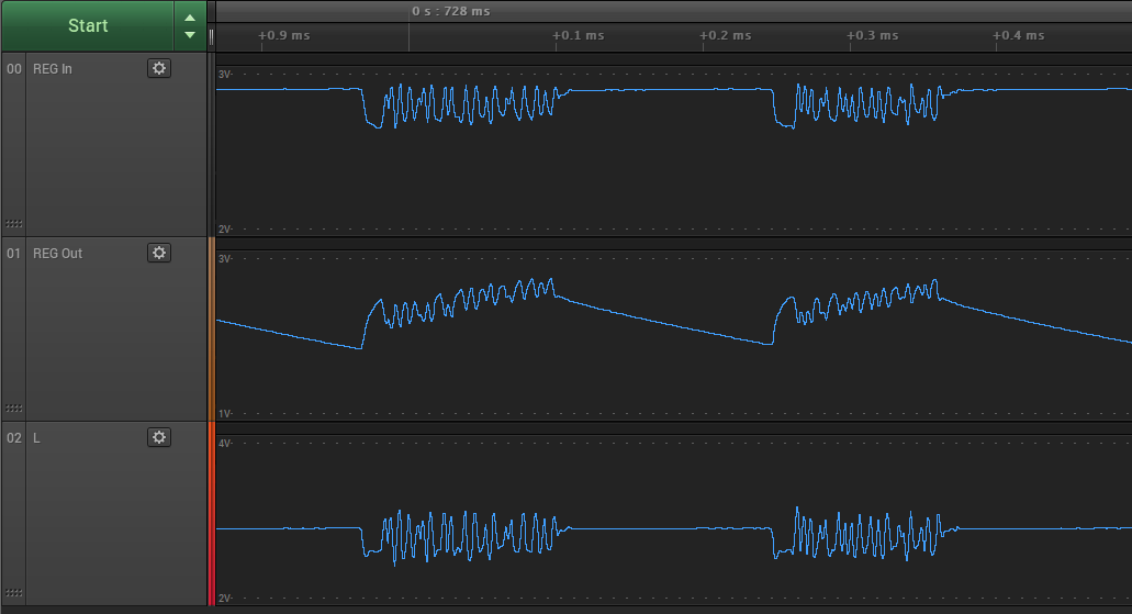
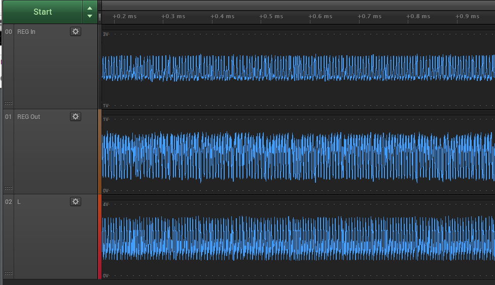
Ultimately I am finding the TPS61201 isn't able to deliver more than 100-200mA or so before the output voltage collapsing or the input current getting very high.

My output power requirements are 3.3v with upwards of 200-250mA for up to 2 min sustained.

My input power requirements are at most 3v batteries, but ideally 1.5v or less.

As I've said if I use a 1.5v battery, the input current is extreme (800mA+) for minor loads.

I believe I've wired the regulator correctly.  I've also used the regulator in a breakout board and produced the same results.

Can you give some feedback on what I might be doing incorrectly if I'm experiencing these results?

Or tell me if I'm attempting to use the device incorrectly in my expectations?

Thank you.

doug

  • could you check if the IC is damaged? you can measure the impedance between the SW and GND pin?
  • Hi Jasper,

    I have used multiple ICs, all seem to exhibit this behavior.

    > measure the impedance between the SW and GND pin

    SW means the L (inductor) pin?
    Are you asking about AC impedance? Or DC resistance? I don't have a way to test AC impedance.
    And do you mean the bare module L pin to PGND? Or a module with the inductor and caps, etc?

    Thanks.


    doug
  • hi
    1. could you measure the Vbat, L and VOUT PIN waveform when you observed issue?
    2. you can use multimeter to measure the DC resistance between L pin and GND pin to check if the IC is damaged
    the blog may help us to quickly debug the issue
    e2e.ti.com/.../tips-in-debugging-a-boost-converter
  • Hi Jasper, thank you, I am following up on this shortly but have been delayed.  Hope to reply with results soon.

    Thanks.

    doug

  • Hi Jasper,

    I have taken both the measurements you asked for.

    > 1. could you measure the Vbat, L and VOUT PIN waveform when you observed issue?

    Yes, here is a scope capture where Vbat="REG In", L="L", and VOUT="REG Out".

    I have three screenshots:

    • Constant draw of 50mA
    • Constant draw of 200mA
    • Constant draw of 500mA

    In all cases:

    • The power supply providing power to the regulator is set to 3.0v
    • Regulator PS=HIGH (disabled)
    • UVLO tied to VIN
    • VAUX 10uF cap to GND
    • VOUT 10uF cap to GND

    Here is constant 50mA draw:

    Here is constant 200mA draw:

    Here is constant 500mA draw:

    > 2. you can use multimeter to measure the DC resistance between L pin and GND pin to check if the IC is damaged

    I did do this.  The device was disconnected from all power, all pins disconnected, no caps nor inductors present.

    The reading is approx 5 mega-ohm between L and GND (same as L and PGND).  Leaving the probes in slowly causes the resistance to decrease over time.

    > the blog

    I will read through the blog and look for issues I may have.

    Thank you again for the help.

    doug

  • is there long cable between the power supply and the IC? why does VBAT voltage oscillate? you may need to add input capacitor to stabilize the input voltage.
  • Hi,

    I swapped the input power source for a pair of AA batteries and similar ripple.  I added a large (47uF) cap and that did smooth the input more.

    However, the fluctuations on the L and VOUT pins remained chaotic.

    What else can I do to diagnose this?

    At the moment I am testing on a breakout PCB for the regulator, as opposed to the genuine product I built using the regulator before.

    For my breakout, I am using the correct inductor (2.2uF power inductor 1.2+Amps), but my output caps (10uF) are electrolytic instead of ceramic.  However, the waveforms I'm seeing in my test setup match what I saw on my PCB when using output caps of ceramic (10uF).

    Layout of the components near the regulator was stated to be important, which I have limited control over in my test setup.  Also, since I see similar waveforms on my PCB, I don't assume layout is to blame because it's so different.

    Can you think of most-likely issues which can affect this?

    Do you agree that the performance I'm getting from the regulator is not what I should expect and that there is some issue?

    Thank you.

    doug

  • yes. this is not expected behavior. there should be some issues. could you share your old PCB and current PCB?
    i would also suggest you apply an EVM for reference.
    please note that do not use electrolytic capacitor instead of ceramic cap.
  • Hi Jasper,

    I purchased a TI evaluation module from DigiKey.

    https://www.digikey.com/product-detail/en/texas-instruments/TPS61201EVM-179/296-31237-ND/1908016

    I will take a few measurements and get back to you.

    Thanks.

    doug