This thread has been locked.

If you have a related question, please click the "Ask a related question" button in the top right corner. The newly created question will be automatically linked to this question.

UA723: "Drift is a one-time thing (“zener walkout”) that stabilizes after time", Output voltage is drifting during test.....!!!!!

Part Number: UA723
Other Parts Discussed in Thread: LM723

Hello, We're using the UA723 in Our power supplies product instead LM723CN from STMicro (is obsolete now and We can't get from any vendor), the problem with the currect UA723 from Texas Instruments is that Output Voltage is drifting during test and this take 3 or 4 times more than normal when We use the LM723CN chip. I read one old article that this problem was reported to TI some time ago. Look below:

"From Kyle Van Renterghem (TI employee)"

For documentation sake, I am posting what was learned and the mitigating steps that can be taken by the user in case anyone else comes across this issue in the future.

Due to the process technology when this device was released (1972) some devices/lots exhibit signs of Zener Walkout which caused the output voltage to change over time (it can possibly take minutes for the output voltage to settle to it's final value). Zener Walkout occurs due to trapped charges during the fab process and will cause a Zener voltage to change and since a Zener is used to create the voltage that the output voltage is referenced to you see a corresponding change in the output voltage. The unfortunate part about this is that it can take minutes for a device to settle while the production tests that a device are significantly shorter so these types of failures cannot be screened out. Since the number/amount of trapped charge is variable due to normal process variations it may not be seen on every lot which explains why your old unit’s/designs didn’t exhibit the problem in the same circuit.

Knowing all of that but not knowing the scale of the number of devices you’ll be producing I see three potential work arounds for you

  1. Screen units by testing the output over time to see if they change, if they don’t change then they are production worthy and use accordingly (obviously this is only feasible for small scale)
  2. Burn in units at high temp to move the trapped charges. This should yield a higher percentage of usable parts.
  3. Migrate the design to a new device.
    1. If you provide us with the design specs for this power solution and we may be able to find a newer device that is run on a much more modern fab process or one that doesn’t use this topology of using a Zener to create the reference voltage

    2. I need Your support, actually there isn't possible to get the LM723CN and We can't change the boards layout for a new I.C, We need to get a fix using the UA723 from You. Plastic Dual In Line with 14 pins is the version that We use. I tried to get a fix using a external diode zener on the Vref pin or adding a 1uF capacitor, but until now nothing works. It's urgent for me get an answer, options, etc...ASAP, because next month We have many product to build. Our company is S.L Power Electronics and We build power supplies to sale.....
      1. Thanks in advance.....
  • Hi Eleazar,

    have you read this document?

    www.ti.com/lit/an/snoa590b/snoa590b.pdf

    See figure 7.

    Kai
  • Hi Eleazer,

    I have some questions to help us to provide the best guidance possible:

    • What is your input voltage, output voltage, and load current?
    • Is the reference drifting proportionally to the output voltage?
    • Are you measuring the voltages with a DMM or looking at it with a scope?
    • When you say drift, are you talking about the output changing vs temperature or vs time?
      • Can you provide scope shots which show the phenomenon (include inputs and output on the same plot if possible)
      • How much drift are you seeing?
    • Are you seeing this drift for every device or just some devices?

    This is a very old device and therefore it has a pin out which we do not have a pin to pin replacement for, so swapping it for a modern device won't be an option. 

  • Hello Kyle,

    What is your input voltage, output voltage, and load current?

    The inout voltage is 18.60VDC, the output voltage is 5.XXXVDC and the output load current 12A (but I'm applyin on my experiment 3.25A)

    Is the reference drifting proportionally to the output voltage?

    Well, the first read on the output was 5.088V (first sample) and the Vref was 7.18V...then after 12 minutes:

    Output voltage = 5.196V   and Vref =  7.27V

    Are you measuring the voltages with a DMM or looking at it with a scope?

    With DMM, is very similar to the method that use Our ATE.

    When you say drift, are you talking about the output changing vs temperature or vs time?

    Output changing Vs time, check my experiment and data below (it was with a second I.C sample)

                Output Voltage                                                     Time                                                      Readings with DMM Fluke 8845A

    5.070V   (read at start up)

     After   1 minute

               5.125V


         "      2 minutes

               5.145V


          "     3 minutes

               5.157V 


           "    4 minutes

               5.165V


          "     5 minutes

               5.172V


          "     6 minutes

               5.177V


          "     7 minutes

               5.180V     


          "     8 minutes

               5.182V


           "    9 minutes

               5.183V


           "   10 minutes

               5.184V

    Are you seeing this drift for every device or just some devices?

    All components have this behavioral (100%) and this is a nightmare for Our test operator (some power supplies have from 1 output to 5 outputs)

    This is a very old device and therefore it has a pin out which we do not have a pin to pin replacement for, so swapping it for a modern device won't be an option.

    Yes, We know that but unfortunately or fortunately We still manufacturing in one of our production lines:  linear products that are old design. We can't redesign the boards (isn't cheap). The LM723CN is obsolete now on the distributors sites, the only active product is your UA723 I.C and We need to get some fix for this issue. This is my work email: eleazar.galvez@slpower.com I hope You or some of Your technical engineers can help Us.


    Thanks in advance....


  • Hi Eleazar,

    you wrote: "I tried to get a fix using a external diode zener on the Vref pin or adding a 1uF capacitor, but until now nothing works."

    You must not connect the external zener to the REF pin, of course!

    Have you read this document?

    www.ti.com/lit/an/snoa590b/snoa590b.pdf

    See figure 7.

    Kai
  • Hi Eleazar,

    Unfortunately what I think you are dealing with is the output voltage drift vs temperature. I know you said that it is changing vs time, but from your input conditions I can see you are dissipating a lot of power (I assume you are using this device to control an external FET) which indicates that the IC and your board is probably getting pretty warm. As a general rule it usually takes around 5 to 10 minutes for a board's temperature to stabilize. Your measurements show this kind of stabilization, Vout increases by 20mV in the first minute but then only goes up by 1mV in the last minute. The only way to reduce the drift would be to reduce the junction temperature of the device.

    However, I was wrong about us not having another compatible device, there is the LM723 which is available in a -55C to 125C version. I think this should address your problem. The UA723 is only specified from 0C to 70C, which may be why you are seeing more drift from it than your previous supplies.

    www.ti.com/.../LM723
  • In fact the Vout was increased by 55mV, from the first meausure and after 1 minute You can see below:

            Output Voltage                                                     Time                                                      Readings with DMM Fluke 8845A

    **5.070V   (meausure at start up)

     After   1 minute  ----------------------->>>

               5.125V

       My experiments confirm the Zener Walkout (one time) issue, all the I.C's are more stable for regulation after the first test (my test bench is around 10 minutes)

    materials department found 4k pieces from the LM723C (Texas Instruments I.C, plastic dip or case) but looks like that was the last pieces on the market. Again in the near future We're going to have the same issue to found more I.C's. The only solution that I found until now is test the I.C's in a test fixture before to use on production floor or wait around 1 or 1.5 minutes to warm the I.C and after that continue with the test. I tried some fix with a zener on pin 6 across the resistor but doesn't work. And again the UA723 has 100% of this problem not is an isolate issue......!!!!!!!!

    This is my update.....

  • Hi Eleazarm

    I'm glad to hear that you confirmed the issue wasn't just the board heating but that it seems to be related to the Zener Walkout discussed in my original post. Unfortunately this is a process dependent issue so there isn't anything we can do to fix it given that this process technology is more than 45 year old.

    There is a high grade version of the LM723 device (LM723H and LM723H/NOPB) still available, however they are significantly more xpensive.
  • O.K, Kyle....

        If after many experiments the only option is to test the I.C's, my next question is:

    Is necessary to test functionally 100%..?? I mean working the I.C direct on the power supply or Is there another way..? maybe applying only Vcc or direct voltage on the pin 6...?  because if I need to test the I.C direct on the power supply with load, etc....my production output are going to be low, but if there is a test fixture where I can put 20 .... or 50 UA723 "only" applying Vcc or DC voltage on pin 6 my output are going to be more higher....!!!!

    Could you please check these options with your technical support engineers or group..??

    Thanks in advance......

  • Hi Eleazar,

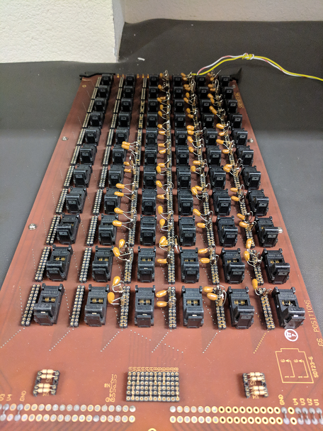
    Yes doing it one by one will be very time consuming. I would recommend creating a test fixture which has many sockets that you can load many parts into and power them up at the same time.  The goal is to power up the devices while they are at high temperature for at least a few minutes to cause the trapped charge in the Zener to move, you can do that in  a couple different ways.

    1. Put the board with the devices into an oven at 125C and power on the devices with minimal load 
      1. Positives: This makes it easier to find a usable input power supply since you don't have a lot of current being drawn from the power supply3
      2. Negatives: Requires an oven, ovens can take a while to get to temp so the more units on the board the more efficient this approach will be. 
    2. Increase the power dissipation to self heat the silicon
        1. Positives: Don't need an oven and the silicon will get to temp very quickly 
        2. Negatives: Less exact way of heating the die, you should going in and out of thermal shutdown (with the output turning on and off), and you need to make sure you have a supply or multiple supplies (with the board laid out for multiple supplies) that can handle the potentially large amount of current

      Below is an example of a board that is made to go into an oven with ~80 units 

    3. O.K, thanks Kyle....!!!