This thread has been locked.

If you have a related question, please click the "Ask a related question" button in the top right corner. The newly created question will be automatically linked to this question.

LM2576: Negative voltage from positive buck converter

Part Number: LM2576

Dear readers,

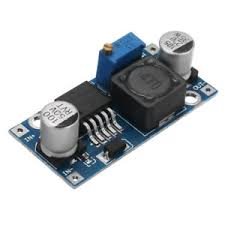
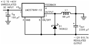
Every now ad then I need a negative power supply with a reasonable power.  At ebay a and aliexpress the LM2576 positive output buck converters modules are sold cheap see fig1 and according schematic depicted in figure 2. Schematic 3 is an example of a buck converter with a negative power output coning from the TI LM2576 data sheets.

I examend the two schematics and looked for the differences. I noticed that basically only the negative lead of the input capacitor has a different position between the two schematics. In fig2 it is connected to the ground and in fig3 to the output. From a module perspective the changes are  that the output has changed label from output to ground,  and the ground has changed label to  negative output. Physically nothing has changed much except for then negative lead of the input capacitor.

Q1: Since this is so deadly simple I wonder if I'm making a thinking mistake. Can someone confirm if my idea to convert these modules to negative output modules is correct or not ?

Q2: If it is correct then I do have and other question. Why is the output current of the negative schematic fig3  0.7 A and not 3 Amp as it is for the positive buck power supply?. Can that be boosted somehow?

Hopefully one of you reads this and can tell me what is right or wrong here.

Regards Oscar Goos.

Fig 1: Module for sale at ebay and aliexpress

Figure 2:  Positive buck converter

Figure 3: Negative buck Converter

  • Hello Oscar,

    Fundamentally you are correct. the input negative lead goes to the output in answer to Q1. If you are trying to use this rule with a module for example, you may run into issues because the device will see Vin+Vout in a Buck Boost (BB) as the output flies negative, where the negative output is the device Ref (0V), as opposed to just Vin for a Buck.

    Regarding Q2, the reason is the INDUCTOR (AVE) current becomes Iinave+Iout for a BB, so the current handling capability of a given device is reduced.

    where Iinave=Pin/Vinmin

    Where Pin = Pout/Efficiency.

    hope this helps?

    David.

  • Hi david
    Nice that you respond. Assuming that I only use a buck mode inverter and not a Buck Boost, do i understand you well that you agree with my idea that it's easy to modify his type of modules to create a negative voltage with reasonable power.

    About the current reduction, I read, later after I wrote this question, that the output current is reduced by a factor of (1-D) with D the duty cycle. how that impacts this module is not fully clear to me but it seems to depend on the Duty-cycle D. Since the voltage in en out also depend on the duty-cycle I assume that the 0.7Amp refers to a 45volt input witch.It might be that the current might be higher in case the input voltage is closer to 12 Volt. Does this ring a bell.