


I'm using the LM3478 controller in a boost converter. The specifications are:
Input voltage: 24V
Output voltage: 30V
Output current max: 8A
Output current min: 100mA
I attach the schematic currently in use.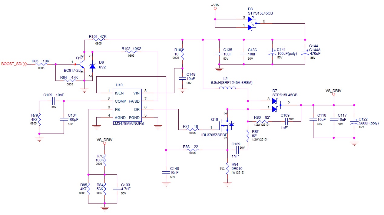
When the output current is minimum, the energy stored in the inductor during the minimum TON of the mosfet is greater than the energy consumed by the load therefore, the LM3478 stops switching as soon as the overvoltage threshold is reached.
This is OK but in this situation the VCOM voltage (output of the transconductance error amplifier) is somewhat different from one device to another.
For example, one LM3478 has a VCOM that varies between 1.63V and 835mV while another LM3478 has a VCOM that varies between 1.52V to 849mV when going from operating to overvoltage. The VFB voltage is almost the same in both devices. This in turn has an effect on the inductor current that the LM3478 will require when it switch on again after overvoltage; greater the VCOM voltage greater the inductor current during the first siwtching cycles. Sometimes even 18A can be forced while other devices does not force more than 7A. I suppose that this variability is induced by a variability of the error amplifier transconductance.
Can you please confirm me if the device is affected by such a variability or do you think that my compensation network could be the problem? In that second case, can you please suggest me the right compensation network components?

