This thread has been locked.

If you have a related question, please click the "Ask a related question" button in the top right corner. The newly created question will be automatically linked to this question.

TPS61232: Problem for unstable Vout on power off sequence

Guru 19495 points
Part Number: TPS61232
Other Parts Discussed in Thread: TLV62080,

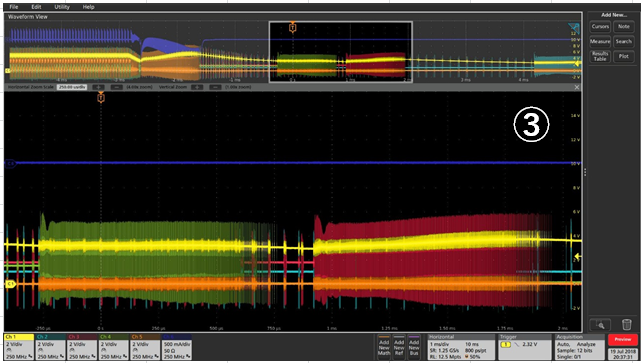
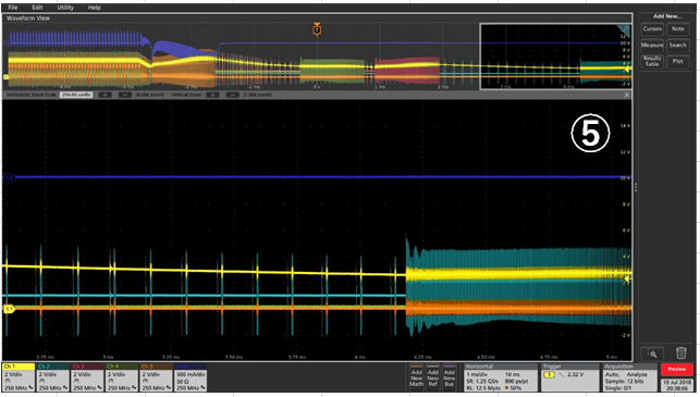
When power off sequence for TPS61232 (and TLV62080) power line, TPS61232 and one of TLV62080 Vout are unstable.

Please let me know about the reason of unstable power down and any idea for proposed measure.

【Additional information】

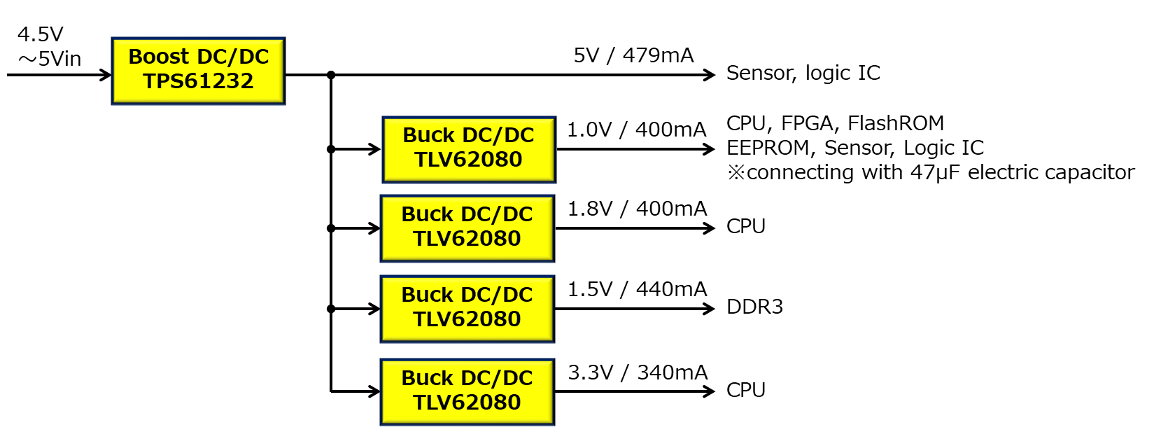
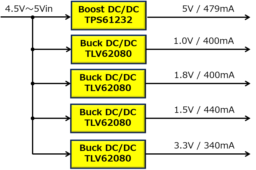
・Power line is attached below block diagram;

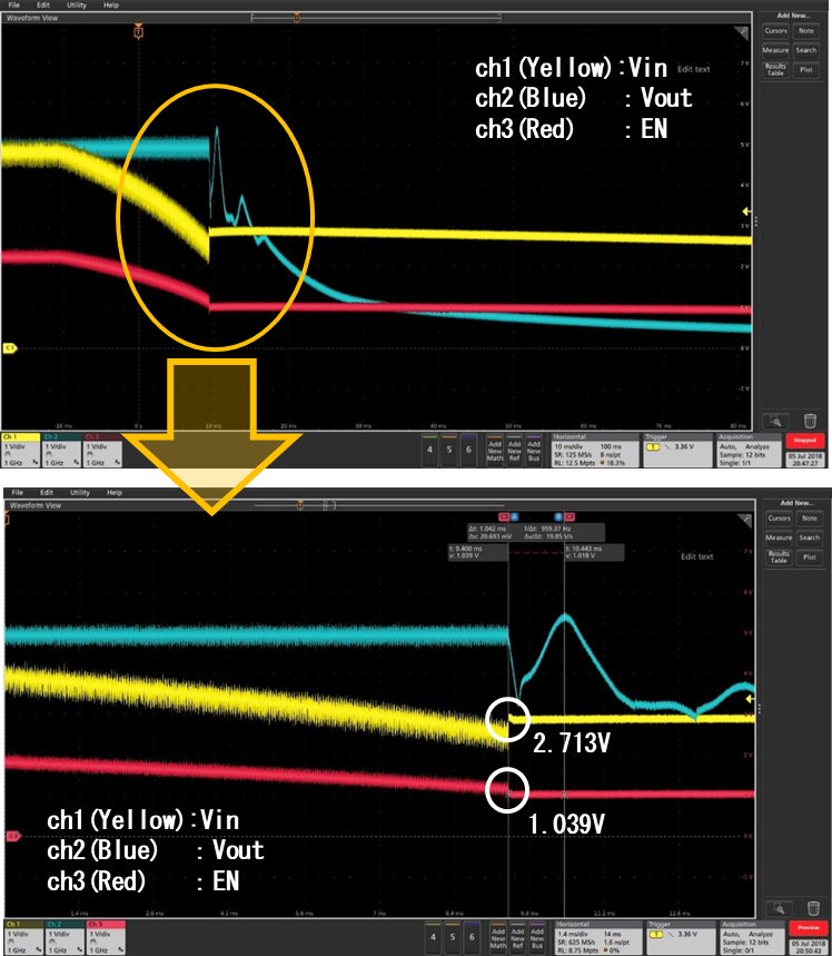
・TPS61232 schematic and waveform is attached below

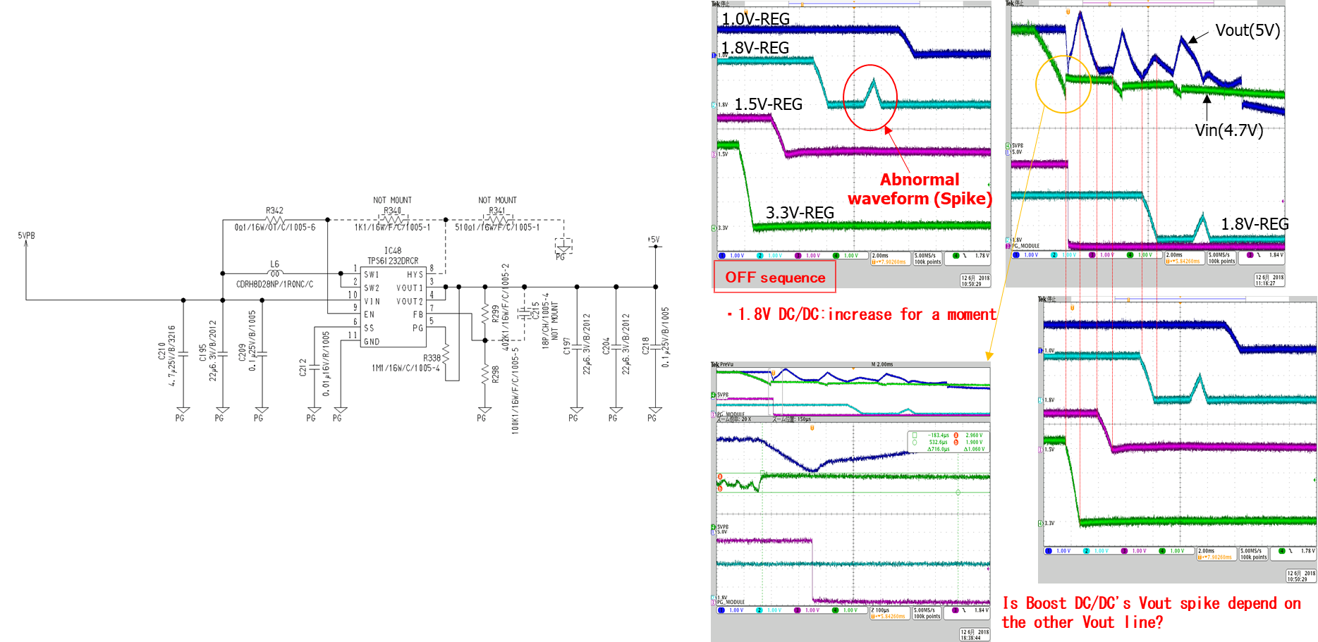
・When TPS61232 set hysteresis, 1.8Vout line was clear. ※Vin_off = 2.4V, Vin_on = 3.5V

 But TPS61232 Vout is not clear. 

Best regards,

Satoshi

  • could you measure the EN pin waveform of TPS61232? the device should shutdown from the input waveform
  • Jasper-san

    Thank you for reply,

    Do you want EN pin waveform for configured hysteresis version?
    If yes, customer will measure waveform, please wait a little time.

    About non-configured hysteresis version, I think that EN waveform is same as Vin waveform.
    Because EN pin is connect to Vin by 0Ω resistance.

    【Additional information】
    4.5V~5V input voltage is supplied from the other board's 5V supply, not stabilized DC power supply.

    Best regards,
    Satoshi
  • yes. waveform of EN with hysteresis version.
    With EN connected with VIN, the device would shutdown at VIN=2V, and turns on at VIN=2.1V.
    so it is not surprise to see start up/shutdown of this device.
  • Jasper-san

    I got waveform of EN with hysteresis version, please see attached below.

    ※Both voltage scale are 1V/div, time scale is 10ms/div and 1.4ms/div(zoom).

    If there any noticed point, please let me know.

    Best regards,

    Satoshi

  • the EN signal shows that the TPS61232 is disabled. could you measure SW pin of the TPS61232 to check if the VOUT ramping up is caused by the switching of the TPS61232.
  • Jasper-san

    Thank you for advice, I attached waveform with Switching voltage below,

    By the way, Cin added 22.6μF to 47μF ×2, I look like Vout swing became large.

    Is this result any hint to you? 

    I guess that TPS61232 power off problem is influence by switching Zero Duty Cycle mode to PWM mode.

    Could you please let me know what you think about my guess?

    Best regards,

    Satoshi

  • Satoshi-san

    Sorry, but i'm not agree with you. We can see from the waveform that the TPS61232 has stop switching when the VIN is lower than the setting voltage. This is why we see the VOUT decreases. And the voltage in SW pin is equal to VIN after the TPS61232 stops switching.

    As the SW voltage is lower than VOUT after the SW not switching, the ramp up of the VOUT is not caused by the TPS61232, but the energy from somewhere in your system connected to VOUT pin. please help to check what is connected to the VOUT of the TPS61232

  • Jasper-san

    Thank you for reply,
    I confirmed Vout connection, please see below.
    ・3.3V:CPU、FPGA、FlashROM、EEPROM、Sensor、Logic IC
     ※3.3Vout line is connecting with 47μF electric capacitor.
    ・1.8V:CPU
    ・1.5V:DDR3
    ・1.0V:CPU

    By the way, 5Vin is made by below AC/DC.
    product.tdk.com/.../info

    Best regards,
    Satoshi
  • Hi Satoshi-san

    Thanks for the detail. It seem other rails should not cause the ramp up of the 5V rail. May I know what is connected to the 5V output rail (TPS61232 output)?

    Is it possible that we can disconnect the system load of the 5V rail, then use the electronic load instead of the system load?
  • Jasper-san

    5Vout line is update, please see below,

    ※Sorry, previous customer block diagram is mistaken, below is correct.

    Best regards,

    Satoshi

  • Any update on this?
  • Hi Satoshi-san

    Sorry for missing your last reply.
    Could you measure the SW voltage of each buck, together with VOUT? I want to check if VOUT rising up is caused by the reversed energy from the buck.
  • Hi Satoshi-san,

    Could you also measure the inductor current of each Buck converter?
  • Jasper-san

    Thank you for advice,

    I got waveform is attached below;

    Inductor current is captured only 3.3V line because the cause of customer board and scope condition. 

    ※ch1(Yellow): 5V boost out, ch2(Light blue): 1V buck out, ch3(Red): 1.8V buck out, ch4(Green): 1.5V buck out, 

        ch5(Orange): 3.3V buck out, ch6(Blue): 3.3V buck inductor current 

    Customer hope, idea for measure are change only resistor or capacitor value, is it possible?

    I think that measure is add reverse protection diode on buck DC/DC, is it correct?  

    Please let me know any idea for measure.

    Best regards,

    Satoshi

  • Hi Satoshi

    1. It would be easier to locate the root cause if we add diode in the input of each buck.
    2. Another solution is disable the BUCK through EN pin when the input voltage of the boost converter is power off.