This thread has been locked.

If you have a related question, please click the "Ask a related question" button in the top right corner. The newly created question will be automatically linked to this question.

LMZ21700: IC failure in new design

Part Number: LMZ21700

Are there any known issues with this device?  I have experienced a failure in a new design after about 20 hours of normal operation.  The device steps 12V down to 5.2V.  The output impedance to ground now measures about 1.4ohms and the output voltage is zero.  The device is very warm.

5V Switcher-5V Switcher B.pdf

  • Hi Andrew,

    What type(static or dynamic) and value of loading do you have on this 12Vin/5Vout circuit? Also, if you power cycle the device, will it work again or does the output stay low indefinitely?

    From your description it sounds like an output short to ground. I will take a look at your schematic to see if there is anything that sticks out.

    Regards,

    Jimmy 

  • Hi Andrew,

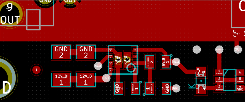
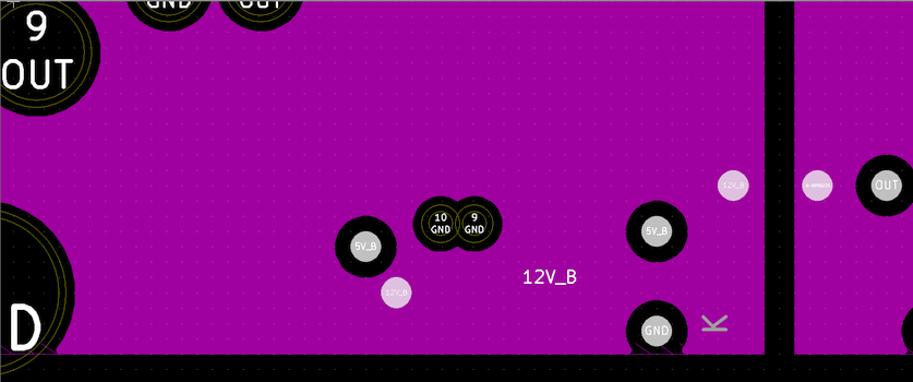
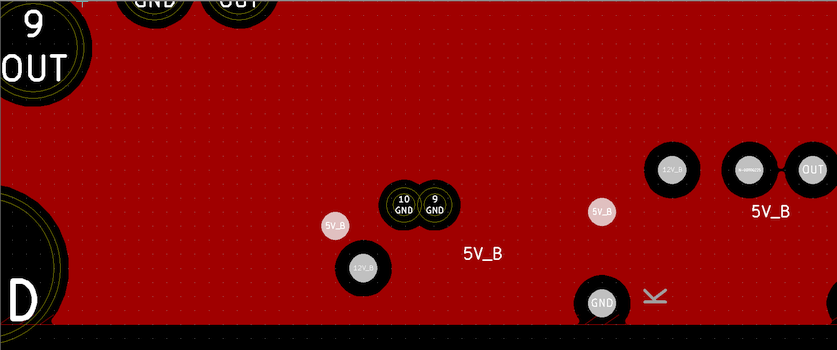
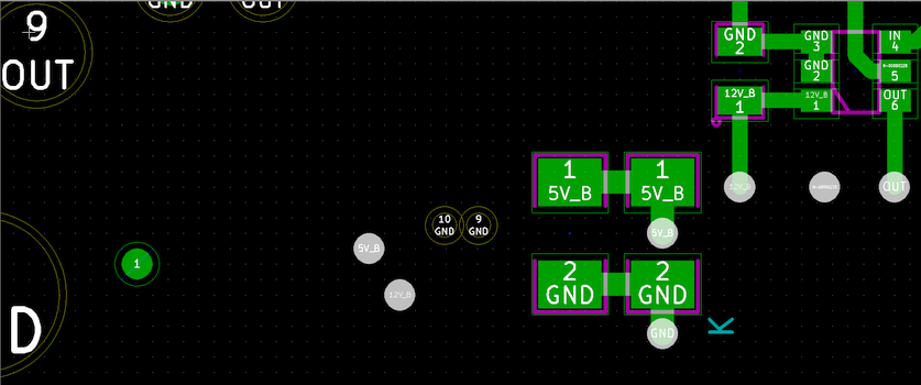
    From the PCB layout, one recommendation that I have is to have a dedicated VOS trace going to a VOUT plane. Layer 5 on your PCB shows an entire VOS copper plane. Since VOS is a sensitive node, a big plane can result in noise coupling into the VOS pin and affect the internal circuitry. Any high frequency noise in the surrounding system can potentially be coupled into the switching regulator.  It is recommended to follow Section 11.1.2 of the datasheet to better immunize from a noisy environment. 

    Out of curiosity, for the 50% failure rate, what was the overall number of failed? 

    Regards,

    Jimmy

  • Hi Jimmy,

    Thank you for your response.

    Re VOS node being connected directly to the power plane, duly noted.  I will adjust this if/when a board revision takes place.

    The load on the LMZ21700 is a single digital IC with 100nF of decoupling, plus a 3.3V regulator with 2.2uF of input capacitance via a series diode and a TPS259573 eFuse IC with an additional 100nF of input decoupling.  The LMZ21700 failed during operation, not on start-up.

    The board is new; only 2 devices have been tested and one of them failed.  The other device has now been running for about 50 hours and is fine.

    Kind regards,
    Andrew

  • Power cycling the failed LMZ21700 produces no change.
  • Hi Andrew,

    There is nothing in the schematic that might cause a low impedance reading between Vout and GND.  Your description further shows that something internal to the PCB or device causes the low impedance on Vout. For the failed board, I'd recommend submitting a customer return for FA through this link so we can further investigate the failure mechanism. 

    Regards,

    Jimmy 

  • Thanks Jimmy.
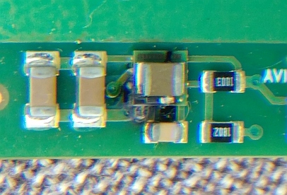
    The LMZ21700 eventually failed catastrophically and was removed from the board. 5V was injected at the output and the rest of the board functioned normally again. Sadly the failed LMZ21700 was not salvageable.
    Kind regards,
    Andrew